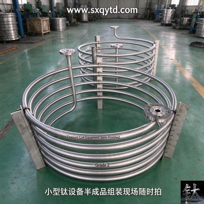
Titanium Tube Vibration: Why a Corrosion Upgrade Fails in Six Months
| Specification | Heat exchanger tube vibration / titanium retube |
|---|---|
| Applicable Standard | Gr2 seamless and welded ASTM B338 / ASME SB-338 condenser tube |
| Material Condition | Connors critical velocity / TEMA Section 6 / baffle span / fretting wear |
| Inspection & Packaging | Vibration analysis report / ITP / tube-to-tubesheet joint / commissioning survey |
Product Description: Titanium survives 20 m/s seawater where Cu-Ni fails near 3 m/s, but critical velocity does not rise with it. Connors K, baffle span and a 14-line PO.
Product Overview
Titanium Tube Vibration: Why a Corrosion Upgrade Fails in Six Months
A titanium retube is bought to end a corrosion problem, and it usually does. What it also does is replace every dynamic property of the bundle without anybody opening the vibration calculation. Published screening data put Grade 2 titanium at roughly 0.3 mpy general corrosion even at 36.6 m/s seawater velocity, while copper-nickel condenser alloys begin to suffer erosion-corrosion above about 3 m/s in sulphide-polluted water, and titanium bundles are routinely operated above 20 m/s. That sevenfold headroom in flow velocity is the commercial reason to buy titanium. It is also the reason the retube fails: the shell-side velocity rises, the tube wall is thinned because no corrosion allowance is needed, the baffle spacing is inherited from a tube with different mass and stiffness, and the critical velocity for fluidelastic instability does not rise with the corrosion allowable. Failure then arrives at a baffle hole or at the expansion transition, commonly within six to eighteen months, on a bundle whose material certificate is perfect.
This guide covers the layer between the material decision and the vibration analysis: what TEMA and the Connors-form criteria actually require, why the published K values disagree by a factor of four, what a thinner wall does and does not change in the natural frequency, how to read an unsupported-span calculation, where the tube physically breaks, and the 14 lines that put the analysis into a purchase order. Our B338 ordering-by-failure-mode guide already states the right conclusion in one paragraph: the titanium modulus is roughly half that of steel, the walls are thin, and retrofits that reuse the original Cu-Ni baffle spacing are a documented source of failure. Our five real tube bundle failure cases gives Case 5 to vibration fracture and sets an empirical red line of baffles for tubes longer than 2 m at 500 to 800 mm spacing. Our process equipment buyers guide covers medium, pressure and the design code. None of the three is a vibration calculation. This article starts at the boundary where a material substitution becomes a structural redesign, and keeps those three as the references for grade, failure history and code respectively.
At a Glance: Nine Checks Before a Titanium Retube
| Item | What the buyer must know |
|---|---|
| The short answer | A titanium retube is a corrosion decision that silently changes the dynamics of the bundle. The tube survives the water, then fails at a baffle hole or at the expansion transition six to eighteen months later. The mill certificate is silent on both |
| The number that explains it | Published screening data put Grade 2 titanium at about 0.3 mpy general corrosion even at 36.6 m/s seawater velocity, while copper-nickel condenser alloys begin to suffer erosion-corrosion above roughly 3 m/s in sulphide-polluted water. Titanium is routinely run above 20 m/s. Corrosion allowables and vibration critical velocities are unrelated numbers |
| The code gap | TEMA 9th Edition Section 6, the V paragraphs, addresses flow-induced vibration, but published engineering commentary notes that section is not metricated and that the TEMA guarantee does not cover vibration damage. A vessel can be fully code compliant and still have no vibration calculation behind it |
| The K-factor conflict | The Connors-form critical velocity uses an empirical constant K. Published values include 9.9 from Connors 1970, 3.3 from Gorman and Pettigrew-era design guidance, 4.0 from one ASME recommendation for triangular pitch, 2.4 as a conservative universal ASME value, 2.8 in TEMA and GB-151 for triangular pitch, and 3.0 recommended by Pettigrew. That is a fourfold spread in the predicted critical velocity |
| The modulus myth | Titanium has about half the elastic modulus of steel, but also about half the density. Natural frequency scales with the square root of E divided by density, not with modulus alone. On the thin-wall beam approximation the two nearly cancel, so a titanium tube and a steel tube of the same OD and span have similar dry frequencies |
| What thin wall really costs | Reducing wall from 1.65 mm to 0.7 mm barely moves natural frequency, but it removes the wear allowance, weakens the rolled joint and shortens the time a fatigue crack needs to cross the wall. Thin wall is a life problem, not primarily a frequency problem |
| The span is the lever | Natural frequency varies inversely with the square of the unsupported span. A published worked example for a 19.05 mm water-filled tube gives 223 Hz at 400 mm span, 99 Hz at 600 mm and 56 Hz at 800 mm, with critical velocity falling from about 7.5 to 1.9 m/s. A spacing red line copied from a case study is not a calculation |
| The one document to demand | A 14-line retube PO and vibration ITP naming the analysis method and edition, the K value with its source, the mass-damping and added-mass assumptions, the critical velocity and margin, the unsupported span map, the tube-to-baffle clearance, and the commissioning vibration check |
Read rows two, three and four first. The recurring failure is not that titanium is a bad condenser tube; it is that a corrosion upgrade was executed as a like-for-like tube swap. Every number in this table has a published source behind it, and several of them conflict. Where the sources disagree we name the disagreement and give the verification action rather than printing one false-precision value. Treat the table as a list of decisions the designer, the fabricator and the tube supplier must settle before a retube is priced. A stockholder can certify OD, wall, heat number and NDT. It cannot decide your baffle spacing, your damping ratio or your inlet velocity distribution. That division of responsibility is the whole subject, and our ASTM B338 tube guide makes the same point for the material specification: the standard gets the tube to the gate, and the purchase order has to carry the duty.
The “Corrosion Upgrade” Trap: Why 20 m/s Is Exactly the Problem
Flow velocity is the one process variable that a materials upgrade deliberately increases. On a copper-nickel or aluminium brass condenser, velocity is capped by erosion-corrosion, so the thermal designer lives with a relatively low shell-side or tube-side velocity and accepts more surface area. On titanium the cap disappears. The passive TiO2 film is not consumed by fast clean seawater, so published corrosion data show essentially no general attack at velocities that would destroy a copper alloy bundle. Designers respond in the honest way: smaller exchanger, fewer tubes, higher throughput on the same shell, or an uprate of an existing unit. Every one of those responses raises the excitation energy in the bundle.
Vibration, by contrast, is governed by a critical velocity that comes out of a stability calculation involving natural frequency, tube mass including entrained and added fluid mass, damping, tube diameter and the geometry of the array. None of those terms contains a corrosion rate. So the two numbers move independently. A material that permits 20 m/s does not raise the fluidelastic instability threshold to 20 m/s; it merely removes the reason the plant used to stay at 2 m/s. Published engineering guidance lists several conditions that push a bundle toward trouble: shell-side crossflow velocity above roughly 2.5 m/s, pitch-to-diameter ratio below about 1.25, wet steam above about 5 per cent moisture, and pressure fluctuation above about 10 per cent of mean, which suggests water hammer. Those are screening flags, not allowables, but they sit an order of magnitude below the velocities titanium is sold to survive.
Corrosion resistance removes the old speed limit. It does not install a new one. The critical velocity has to be calculated for the bundle as built, not inherited from the material datasheet.
This is why uprating is the highest-risk scenario. A vibration analysis provider describes flow-induced vibration as one of the most frequent causes of damage in shell-and-tube equipment and specifically names uprating existing units as a trigger for a fresh calculation. A debottlenecking project that raises mass flow through an existing shell changes crossflow velocity in the inlet region, the baffle window and the bypass gaps at the same time, while leaving every unsupported span exactly where it was. Our titanium versus 316L and 6Mo upgrade ladder warns against treating a corrosion upgrade as a drop-in substitution. The same objection applies one axis over: the upgrade changes the excitation side of the vibration problem as well as the material side.
There is a second, quieter version of the trap. Titanium tubes are frequently specified at a thinner wall than the tubes they replace, because a corrosion allowance of 1 to 2 mm on a steel or copper-alloy tube becomes unnecessary. Our B338 failure-mode guide says this plainly: on a titanium seawater tube the wall is almost entirely a mechanical specification, and removing 0.2 mm to hit a price can cost the joint. A thinner wall reduces the mass per unit length, changes the roller expansion ratio, and cuts the time a wear scar or a fatigue crack needs to penetrate. It is a sound economic decision only if the mechanical consequences are recalculated rather than assumed away.
The Modulus Myth: What E over rho Actually Does to Natural Frequency
Almost every short explanation of titanium tube vibration says the same thing: titanium has about half the elastic modulus of steel, so it is more flexible and more sensitive to flow-induced vibration. The first clause is true. Published handbook values put Grade 2 titanium near 105 GPa with a density of 4.51 g per cubic centimetre, against roughly 195 GPa and 7.85 for carbon steel, about 193 GPa and 8.0 for 316L, and roughly 124 to 140 GPa and 8.9 for 90-10 copper-nickel. The second clause is an oversimplification, and the reason is visible in the beam equation.
For a uniform tube span treated as a simply supported beam, the lowest flexural natural frequency is proportional to the square root of EI divided by m times L to the fourth, where E is modulus, I the second moment of area, m the total mass per unit length and L the unsupported span. For a hollow circular tube, I contains the difference of the fourth powers of outer and inner diameter, while the metal mass contains the difference of the squares. Dividing one by the other leaves the sum of the squares of the diameters. The result is that natural frequency scales with the square root of E divided by density, multiplied by a weak geometric term and divided by the span squared. Using the handbook values above, the square root of E over density is about 4,825 for titanium, about 4,984 for carbon steel and roughly 3,800 for 90-10 copper-nickel, in consistent SI units. On that approximation a titanium tube and a steel tube of the same OD and span have dry natural frequencies within a few per cent of each other, and the titanium tube is actually higher than the copper-nickel tube it replaced.
That result surprises people, so it needs its boundary stated. The cancellation holds for the metal beam in air, where m is the tube mass alone. In a real exchanger the mass term also contains the tube-side fluid and an added-mass contribution from the shell-side fluid, typically written as an added-mass coefficient times the displaced fluid mass. Neither of those two terms scales with the metal density. Because a titanium tube is lighter per unit length, the fixed fluid terms make up a larger share of its total vibrating mass, so the wet frequency of a titanium tube falls proportionally more than that of a steel tube. Published worked examples use added-mass coefficients around 1.5 to 1.6 and damping ratios around 1 to 1.5 per cent as teaching assumptions, and they state clearly that project values must come from the chosen vibration method. That is the honest reason the wet bundle, not the dry metal, has to be calculated.
Now the wall thickness question. Moving from a 1.65 mm wall to a 0.7 mm wall on a 19.05 mm tube changes the geometric term in the numerator only slightly: the sum of outer and inner diameter squared rises a little as the bore grows, so the metal-beam frequency barely moves, and in the pure metal approximation it can rise by a few per cent. Add the fluid mass terms and the effect stays small compared with a change in span. What the thinner wall does destroy is everything the frequency equation does not describe: the wear allowance at the baffle hole, the residual stress and wall reduction in the rolled joint, the margin against a sharp tube-sheet edge, and the number of cycles a fatigue crack needs to cross the wall. So the shop-floor warning that thin walls are sensitive to vibration is right, but it is right about damage tolerance rather than about resonance. Those are two independent checks and both belong in the review.
Our Gr5 versus Gr23 ELI guide and Gr9 versus Gr5 guide settle strength, purity and cold formability. Neither changes the modulus enough to rescue a badly supported bundle: all titanium grades sit in the same narrow modulus band. If a supplier proposes a higher-strength grade to solve a vibration failure, ask which term of the frequency equation it changes. Strength raises the stress the tube can tolerate; it does not move the natural frequency, the critical velocity or the baffle spacing. Escalating the grade is a legitimate answer to a strength problem and an irrelevant answer to a dynamics problem.
Four Excitation Mechanisms, and the One That Kills Quickly
Published design guidance groups shell-side crossflow excitation into four mechanisms, and they do not carry equal risk. Treating them as one phenomenon called vibration is why some bundles pass a check and still fail.
Turbulent buffeting
Broadband turbulence is always present. It produces small random motion rather than a resonant event, so it rarely breaks a tube outright, but it is the mechanism that slowly wears the tube where it passes through a baffle hole or a support plate. Where the clearance is generous and the fluid is dense, that small motion continues for every operating hour of the plant. Turbulent buffeting is the reason that a bundle with an adequate fluidelastic margin can still develop oval or saddle-shaped wear at supports after a few years, and it is the mechanism most closely tied to tube-to-baffle clearance and baffle thickness.
Vortex shedding
Vortex shedding behind a tube occurs at a frequency set by the Strouhal number, the crossflow velocity and the tube OD; published values for the Strouhal number in tube arrays run roughly from 0.2 to 0.5 depending on pitch and layout angle. When the shedding frequency approaches a tube natural frequency, resonance amplifies the response. A published worked example gives a vortex-resonance velocity of 12.9 m/s at 400 mm span, 5.7 m/s at 600 mm and 3.2 m/s at 800 mm for the same water-filled tube. This mechanism is gas-shell and high-velocity sensitive, and it is checked against frequency proximity rather than against an amplitude threshold.
Fluidelastic instability
This is the governing check and the dangerous one. Above a critical velocity the tube motion and the surrounding flow reinforce each other, so amplitude grows abruptly rather than gradually, and tubes can strike neighbours or baffles hard enough to sever within hours or a few months. The classic Connors-form criterion relates the reduced critical velocity to a mass-damping parameter built from total mass per length, damping ratio, shell-side fluid density and tube diameter, multiplied by an empirical constant K. Because the critical velocity is proportional to natural frequency, and natural frequency falls with the square of the unsupported span, the spacing decision dominates this check. This is the mechanism behind the six-to-eighteen-month retube failures that arrive with no corrosion on the fracture face.
Acoustic resonance
A standing acoustic wave in the shell can couple to vortex shedding, mainly in gas or vapour service rather than in all-liquid exchangers. It is a shell-side geometry and speed-of-sound problem, and published design commentary treats it separately at the end of the TEMA vibration section. Remedies include detuning the acoustic mode with baffle or plate arrangements rather than changing the tube. Wet steam, high vapour fraction and two-phase flow complicate all four mechanisms because density and damping become uncertain, which is why two-phase duties attract additional conservatism in the published criteria.
One practical consequence: a vibration report that only shows a fluidelastic instability margin has answered one of the four questions. Ask separately for the vortex frequency comparison, the turbulent buffeting amplitude at supports, and whether an acoustic check applies to the shell-side phase. Our weld NDT and WPS qualification guide makes the parallel point for weld acceptance: four different codes are not interchangeable, and a pass under one does not discharge the others. Vibration checks work the same way.
The K-Factor Conflict: 2.4, 2.8, 3.0, 3.3, 4.0 and 9.9
The Connors-form critical velocity is only as good as the empirical constant K, and published sources do not agree on it. A comparison assembled for nuclear condenser leakage investigations lists an ASME recommendation of 4.0 for triangular-pitch arrays, described in that source as high-risk and rarely used because it is not conservative, and a universal ASME value of 2.4 described as too conservative to be practical. The same comparison gives 2.8 for TEMA and GB-151 on triangular pitch, and quotes Pettigrew recommending 3.0 as a reasonable balance of safety and economy. It then reports a manufacturer using 3.4 for a condenser that repeatedly suffered titanium tube-to-tube fretting, above the common TEMA and GB-151 values. A separate engineering review of published criteria cites Connors 1970 at 9.9 for a tube row with a pitch ratio of 1.42, design guidelines from Gorman and from Pettigrew and co-workers at 3.3, and array-specific lower bounds such as 3.58 multiplied by pitch ratio minus 0.9 and a mass-damping term to the power 0.1. That review warns explicitly that no single criterion applies to all cases because different instability mechanisms dominate in different ranges.
The spread matters arithmetically. Because critical velocity is linear in K, a change from 2.4 to 9.9 is a fourfold change in the predicted threshold. A bundle judged safe at 6 m/s under one published constant is unsafe at 1.5 m/s under another. This is not a discrepancy we can resolve by picking a favourite, and it would be irresponsible to print one number as the answer. Published Chinese-language design literature makes the same point from the opposite direction: all the common calculation methods derive from the Connors formula, and the differences between TEMA, GB-151 and ASME lie mainly in the chosen empirical coefficient. A nuclear condenser investigation concluded that a manufacturer using a K value above the common standard, combined with an assumed uniform inlet flow field, was a direct contributor to repeated titanium tube fretting.
Six actions that settle K for your own project
- Require the designer to name the analysis standard and edition, the specific clause or section, and the K value with its source document. A number without a citation is not an analysis.
- Require the tube array geometry behind that K: pitch ratio, layout angle (triangular, rotated square, square) and flow direction. Several published constants are array specific and cannot be transferred between layouts.
- Require the mass-damping parameter inputs in full: total mass per length with its breakdown into tube metal, tube-side fluid and shell-side added mass, the added-mass coefficient, the damping ratio and the shell-side fluid density with phase noted.
- Require the critical velocity at every governing zone, not only at the bundle average: inlet region below the nozzle, baffle window, bypass and pass-partition gaps, and the U-bend region. A uniform inlet assumption has been named as a root cause in published failure investigations.
- Require the design margin as a ratio of critical to actual velocity, with the operating envelope including start-up, uprate, fouled and two-phase conditions. State who owns the margin.
- Request a sensitivity run at the conservative end of the published K range. If the design only passes at the optimistic constant, the retube has no robust case.
There is a governance issue sitting behind the numbers. TEMA 9th Edition Section 6, the V paragraphs, is the section that covers flow-induced vibration, and published engineering commentary notes both that the section is not metricated and that the TEMA guarantee expressly does not cover vibration damage. Other analysis providers make the same observation: because of the complexity of the phenomenon, TEMA excludes vibration damage from its warranty, which makes an up-front calculated verification more important rather than less. In other words, an exchanger can be built to TEMA, stamped to ASME Section VIII and delivered with a complete data book while nobody has contractually warranted that it will not shake itself apart. That responsibility has to be written into the purchase order. Our process equipment buyers guide lists the design code among the required datasheet fields; the vibration analysis belongs on the same line as a named deliverable, not as an assumed consequence of the code.
This is also where the cross-family substitution problem returns. Our upgrade ladder shows that an or-equivalent clause crossing a passive-film system is unenforceable. A retube that changes alloy family but reuses the original thermal and mechanical design is the same error translated into dynamics: the drawing says the same tube OD and the same baffle layout, so the assumption is that the analysis still holds. The K value, the added mass and the damping have all changed. Write them out.
The Baffle Span Calculation: Why 800 mm Is Not a Universal Red Line
Of all the inputs in a vibration analysis, the unsupported span is the one with the most leverage and the one most often inherited without a calculation. Natural frequency varies inversely with the square of the span, and critical velocity is proportional to natural frequency, so a modest increase in baffle spacing produces a large fall in the allowable velocity. A published worked example for a 19.05 mm OD tube with 1.65 mm wall, water on both sides, an added-mass coefficient of 1.5 and 1.5 per cent damping gives the following pattern, with critical velocities computed at two different K values.
| Unsupported span | Natural frequency | Critical velocity, K = 3.0 | Critical velocity, K = 2.4 | Vortex resonance velocity |
|---|---|---|---|---|
| 400 mm | 223 Hz | 7.5 m/s | 6.0 m/s | 12.9 m/s |
| 600 mm | 99 Hz | 3.3 m/s | 2.7 m/s | 5.7 m/s |
| 800 mm | 56 Hz | 1.9 m/s | 1.5 m/s | 3.2 m/s |
At a gap velocity of 2 m/s the 600 mm case has a margin, while the 800 mm case is already beyond the fluidelastic threshold even at K = 3.0, and more clearly so at the conservative K = 2.4. Those figures are for one specific tube, one fluid pair and one set of assumed coefficients, and we are presenting them to show the shape of the relationship, not as design allowables for your exchanger. What they demonstrate is that a spacing rule of thumb cannot be separated from the velocity at which the plant will actually run.
This is where we have to be careful with our own content. Case 5 of our tube bundle failure article gives a field rule: tubes longer than 2 m need baffle support, with spacing held between 500 and 800 mm, plus a natural frequency recheck. That is sound installation advice and we are not retracting it. It is an empirical red line for the case described, not a substitute for the calculation, and the worked example above shows why: at the upper end of that band a 2 m/s crossflow can already exceed the threshold. Read the two as independent checks. The field rule gets a fabricator to install support where a bundle would otherwise be completely unsupported; the calculation decides where within the band this particular exchanger has to sit. Our custom-drilled titanium baffle plate page is the hardware those two decisions are translated into.
The span map also has to cover the non-obvious spans. The distance from the tubesheet to the first baffle, the window region where tubes pass through the baffle cut, the outlet span, and the U-bend region are each governed by different support conditions and often by different effective lengths. Published design guidance warns that the baffle window zone and inlet and outlet spans need their own treatment and that tubes in the window are frequently the least supported in the bundle. U-bent condenser tube geometry adds the bend region, where the lowest mode and the support grid arrangement decide the response. Our coil selection guide covers bend radius and post-bend condition; the vibration addendum is to give the bend its own support grid and its own frequency check rather than treating it as another straight span.
Remedies, when the calculation fails, are mostly geometric and mostly cheap at the design stage. Reduce the unsupported span by adding baffles or intermediate supports, add U-bend support grids, change the tube layout to rotated square where the vibration performance is better, avoid excessive pitch-to-diameter ratio, add impingement protection or a distributor at the inlet nozzle, or fit damping elements between tubes. Published prevention literature also describes tube-to-tube strips, rods or plates inserted to absorb vibrational energy, helical baffles and rod-baffle designs that improve support and disrupt regular vortex formation. All of them are far cheaper before the bundle is built than after the first tube leaks. Our coiled tubing range and seamless B338 heat exchanger tube stock are the replacement parts; the point of this chapter is that the drawing, not the tube, usually needs to change.
Where the Tube Actually Breaks: Fretting, Sawing and the Expansion Transition
Vibration damage is highly localized. A bundle can be metallurgically perfect everywhere except at four or five repeatable positions, which is why a visual inspection that looks at the middle of the tube finds nothing. Published examinations of titanium heat exchanger vibration describe the same locations again and again.
Mid-span tube-to-tube contact
Under large amplitude motion, neighbouring tubes strike each other and polish a characteristic rhomboid or hexagonal flat at the middle of the span. Thermal expansion increases the relative sliding at the contact and changes the wear pattern. Where joint relaxation and corrosion coexist with the motion, the worn shape is described as saddle-like. This mechanism is why tube-to-tube clearance and pitch ratio appear in vibration screening criteria.
The baffle hole
Tube holes in baffles and support plates are commonly larger than the tube OD, with published figures of about 0.8 to 1.2 mm diametral or radial clearance quoted in vibration-prevention literature. The resulting relative motion gradually thins the wall at the support. When the baffle is thin and harder than the tube, the edge can saw into the tube rather than merely rub it, and the tube can sever. This is a place where the tube material, the baffle material, the hole edge finish and the clearance all matter more than the bulk corrosion rate. baffle drilling and hole tolerance are therefore vibration variables, not just fabrication tolerances.
The tube sheet and the expansion transition
The sharp edge of a tubesheet hole can cut a vibrating tube, and the highest bending stress in a fixed tubesheet design concentrates at the anchor point. Published failure investigations describe fatigue accumulating in the rolled joint region, with cracks starting at the expansion transition where the roller-expanding process leaves residual tensile stress, and tubes failing on the shell side just behind the tubesheet rather than at mid-span or at the U-bend. One source tabulates expansion parameters as red lines: wall reduction of roughly 8 to 12 per cent at the joint with more than 18 per cent flagged as a failure indicator, expansion ratio around 3.0 to 5.5 per cent, and repeated rolling passes as a damage accelerator. Those are published diagnostic values from a specific investigation, not universal acceptance limits, but they show why the joint is a stress concentrator before the flow is even turned on. tube-to-tubesheet welded joint detail and tubesheet material selection guide cover the joint design and the plate choice; the vibration addendum is that the joint has to survive cyclic bending as well as pressure and corrosion.
The weld heat-affected zone
Where a tube is seal welded rather than only expanded, the HAZ is a competing crack-initiation site. Titanium welds that picked up oxygen or nitrogen during GTAW are harder and less ductile, and the local geometry change at the weld root concentrates stress. our GTAW shielding guide sets out the three-zone argon discipline; our WPS and NDT qualification guide covers what the qualification record must contain. Neither record says anything about cyclic loading, so a weld can be fully accepted and still be the weakest link under vibration.
The diagnostic consequence is practical. When a retubed exchanger leaks, ask for the location and the shape of the defect before debating alloy chemistry. An oval wear scar at the first support points to turbulent buffeting and clearance; a rhomboid flat at mid-span points to tube-to-tube impact; a circumferential crack just behind the tubesheet points to a bending-fatigue problem at the expansion transition. Those three findings lead to three different fixes, and a new tube grade is not among them. Our five failure cases is the right reference for the wider failure taxonomy; this section is the vibration-specific branch of it.
What a Retube Changes: Wall, Mass, Damping, Clearance and Uptime
A retube enquiry usually arrives as a single line: replace the existing bundle with Gr2 titanium tube, same OD, same length, same quantity. That line implies at least seven changes to the vibration problem, and none of them appears in the RFQ.
| Variable | What the substitution changes | Where it enters the analysis |
|---|---|---|
| Wall thickness | Corrosion allowance removed, commonly 1.65 mm down to 0.7 or 0.9 mm | Weak effect on frequency, large effect on wear life, expansion ratio and crack-through time |
| Metal mass per length | Density falls from about 8.9 or 7.85 to 4.51 g/cm3 | Total vibrating mass m; raises the relative share of fixed fluid and added-mass terms |
| Modulus | About 105 GPa versus 195 GPa steel or 124-140 GPa Cu-Ni | Bending stiffness EI; largely offset by the density change in sqrt(E/rho) |
| Operating velocity | Erosion-corrosion cap disappears; uprates and higher throughput become possible | Actual gap velocity in every governing zone; the excitation side of the margin ratio |
| Damping | Changed by tube mass, support clearance, fouling and two-phase content | Mass-damping parameter delta in the Connors-form criterion |
| Tube-to-baffle clearance | New OD tolerance band against holes drilled for the old tube | Support effectiveness, impact velocity and wear rate at the hole |
| Expected run length | Buyers expect decades because corrosion has been designed out | Fatigue cycle count; a 56 Hz mode accumulates roughly 4.8 million cycles per day |
The last row is worth spelling out. A tube vibrating at its first mode completes one stress cycle per oscillation. At 56 Hz, the frequency in the 800 mm example above, that is about 4.8 million cycles in a 24 hour day and roughly 1.8 billion in a year of continuous running. A fatigue problem does not need a large stress amplitude when the cycle count is that high, and a material with no corrosion allowance has very little wall for a crack to cross. This is the arithmetic behind failures that appear after six months with no corrosion products and no obvious overload: the plant simply accumulated a billion cycles.
Two of these variables are commonly overlooked because they belong to fabrication rather than design. The tube-to-baffle clearance is set by the OD tolerance band of the new tube against holes drilled for the old one, and our B338 failure-mode guide notes that a tube ordered to average wall can legally contain local thin spots while the OD tolerance drives the expansion ratio. Fouling is the second: deposits add mass to the tube, which lowers natural frequency, and simultaneously narrow the flow channel, which raises local velocity. One mechanism moves the response down and the excitation up at the same time. Our brine lithium extraction exchanger page shows how quickly a fouling-prone duty changes the maintenance picture, and the vibration addendum is to re-evaluate the fouled state rather than only the clean state.
For the stockholder, this table is also a scope boundary. condenser tube stock, B338 tube cut to length and heat exchanger fittings are the items we can supply and certify. The baffle spacing, the inlet distributor, the K value and the acceptance margin are design outputs. Asking a tube supplier to confirm that a bundle will not vibrate is like asking a mill to certify a flange preload: the honest answer is that the evidence sits with a different party.
The 14-Line Retube PO and Vibration ITP Template Buyers Can Copy
The specification failure in this subject is always the same: a material substitution written as a like-for-like tube order. The template below is written so that every line can be copied into a purchase order or an inspection and test plan and answered with a document. It deliberately separates the material standard from the vibration analysis, the clean state from the fouled state, and the mill certificate from the design deliverable. Copy it, delete the lines that genuinely do not apply, and never merge lines four and five.
| # | Line to put in the PO or ITP | Evidence to demand |
|---|---|---|
| 1 | Original bundle: tube material, OD, wall, pitch, layout angle, baffle spacing and quantity | As-built drawing or measured survey, not the original catalogue sheet |
| 2 | Replacement tube: grade, UNS number, ASTM B338 or ASME SB-338 with edition, seamless or welded, OD and minimum wall | Heat-numbered certificate; no or-equivalent clause across alloy families |
| 3 | Governing mechanical design code and the named vibration analysis standard with edition and section | Written designer statement; TEMA Section 6 is not a warranty item |
| 4 | Critical velocity method and the K value with its source, array geometry and flow direction | Analysis report with citation; sensitivity run at the conservative published K |
| 5 | Mass-damping inputs: metal mass, tube-side fluid mass, added-mass coefficient, shell-side density and phase, damping ratio | Input sheet with every assumed value flagged and owned |
| 6 | Natural frequency for every governing span, with end conditions and the beam constant used | Span map tied to the fabrication drawing, including window, inlet, outlet and U-bend regions |
| 7 | All four excitation checks: fluidelastic instability, vortex shedding, turbulent buffeting, acoustic resonance where applicable | Four separate results; a single instability margin is not a vibration analysis |
| 8 | Operating envelope: design, start-up, uprate, fouled and two-phase velocities per zone | Velocity map with the critical-to-actual margin ratio for each case |
| 9 | Tube-to-baffle clearance, baffle thickness, edge finish, baffle material and hole tolerance | Drilling record and OD tolerance band of the delivered tube |
| 10 | Tubesheet joint: expansion ratio and pressure, wall reduction limit, seal weld WPS and PQR if welded | Per-tube expansion record, weld map, qualification package |
| 11 | Inlet protection: impingement plate, distributor or diffuser, and the assumed inlet flow uniformity | Nozzle detail and any flow distribution study; a uniform inlet assumption must be declared |
| 12 | Material and surface controls: free-iron exclusion, dedicated tooling, delivered hydrogen result, weld colour acceptance | Free-iron test, hydrogen result, weld colour photographs, tooling record |
| 13 | Commissioning: vibration or noise survey at start-up and at the uprated duty, plus a baseline record for trending | Signed survey with measurement locations and the acceptance criterion stated in advance |
| 14 | Inspection interval tied to operating hours and cycles, with the named signatories who own the vibration margin | Equipment file entry, deviation route for future uprates, release signatures |
Line four is the one most often left blank, and line seven is the one most often answered with a single number. Line five is the one that separates a competent analysis from a spreadsheet: every assumed coefficient has to be visible, because the published K values and damping data disagree. Line thirteen is the one that makes the calculation falsifiable after start-up. Write the owner of each line next to it. Our EN 10204 3.1 certificate page and equipment arrival acceptance guide are the two references to attach when a supplier asks what evidence belongs with the tube and what belongs with the assembly; B265 plate guide and what B16.5 hides about flanges show the same pattern in their own product families, where a standard gets you to the gate and the PO carries the duty.
One contractual note. Because TEMA expressly excludes vibration damage from its guarantee in the published commentary cited above, the analysis deliverable cannot be assumed to follow from a TEMA class designation. It has to be a named line in the order with a named author, a named revision and a named signatory. heat exchanger fittings and cut-to-length B338 tube are the physical deliverables; the vibration report is the one that decides whether they get to stay in the shell.
Limitations and Failure Conditions: Eight Ways a Titanium Retube Fails
None of the eight conditions below means titanium is the wrong condenser tube. Each one means a variable was inherited rather than recalculated. Several of them are places where the metal was never the problem, and we would rather say so here than in a failure investigation.
Reusing the original copper-nickel or steel baffle spacing in a titanium retube
This is the single most documented retube failure and the one our own B338 failure-mode guide already flags. The original spacing was calculated, or arrived at by practice, for a tube with different mass, stiffness and allowable velocity. Changing the alloy and the wall while keeping the span assumes the analysis is transferable. It is not. Natural frequency falls with span squared, and the worked example in this article shows critical velocity dropping from about 7.5 m/s at 400 mm to about 1.9 m/s at 800 mm for the same tube. Require a new span map and a recalculation at the actual operating velocity, including the tubesheet-to-first-baffle span, the window zone and the outlet span.
Raising throughput or steam load on an existing titanium bundle without a new analysis
Uprating is named in published engineering guidance as a trigger for a fresh vibration analysis because mass flow raises crossflow velocity in the inlet region, the baffle window and bypass gaps while leaving the geometry unchanged. The corrosion allowance of titanium makes the uprate look harmless from a materials standpoint, which is exactly why it gets approved without a mechanical review. Start-up, fouled operation and two-phase conditions can all produce higher local velocities than the steady design point. Require a calculation across the full operating envelope, not only at the nameplate duty, and record the deviation approval if the plant later runs above it.
Tube-to-baffle holes drilled for the old OD, or a thin hard baffle against a soft thin tube
A clearance of roughly 0.8 to 1.2 mm between tube OD and baffle hole is quoted in vibration-prevention literature as normal, but normal is not the same as acceptable for a light thin-wall tube at high velocity. The tube hammers the hole edge, the wall thins, and a thin hard baffle can saw through rather than polish. Thermal expansion increases relative sliding. Specify the delivered OD tolerance band against the actual hole diameter, the baffle thickness and edge finish, the baffle material relative to the tube, and a maximum allowable clearance as a fabrication hold point. Our baffle plate page is where that tolerance has to be written.
Over-expansion or repeated rolling at the tube-to-tubesheet joint
The expansion transition is where bending fatigue concentrates in a fixed tubesheet design. Published diagnostic investigations list wall reduction of about 8 to 12 per cent at the rolled joint with values above 18 per cent flagged as failure indicators, and describe cracks starting where residual tensile stress from roller expansion meets cyclic vibration load. Over-expansion also produces microcracks that can take months to appear, which is the failure mechanism in Case 1 of our five tube bundle failure cases. Keep the expansion pressure and ratio within the qualified procedure, record every tube, and treat the joint as a fatigue detail rather than only a leak-tightness detail. Tube-to-tubesheet joint detail covers the weld alternative.
Two-phase, wet steam or high vapour fraction shell-side flow
All four excitation mechanisms become harder to predict when density and damping vary across the bundle. Published screening flags include shell-side velocity above about 2.5 m/s, pitch-to-diameter ratio below about 1.25, wet steam above about 5 per cent moisture, and pressure fluctuations above about 10 per cent of mean suggesting water hammer. Two-phase flow also changes the added-mass term, which is one of the reasons published K values disagree. Do not apply a single-phase water criterion to a condenser, evaporator or reboiler without stating the phase assumption. Require the designer to name the two-phase treatment and to run a sensitivity case at the conservative end of the published coefficient range.
Fouling, deposits and sponge-ball cleaning changing both mass and local velocity
Deposits add mass to the tube, lowering natural frequency, while narrowing the flow passage and raising local crossflow velocity. The response moves down and the excitation moves up at the same time. Cleaning restores the geometry but not necessarily the support condition: aggressive mechanical cleaning can enlarge a baffle clearance, and a brush or sponge-ball regime that is fine for a thick copper-alloy tube may be marginal for a 0.7 mm titanium wall. Our brine lithium exchanger page shows how quickly fouling drives the maintenance plan. Analyse the fouled state as well as the clean state, and keep cleaning tools within the wall budget.
A weld, a tubesheet or a support made from a dissimilar metal in the same wet bundle
Vibration and corrosion couple at the joint. A carbon steel or copper-alloy tubesheet, a steel support plate or a carbon steel baffle in contact with a large wetted titanium area creates a small-anode to large-cathode galvanic couple, and the area ratio decides how fast the steel is consumed. Our galvanic corrosion guide explains why coating only the anode is the classic mistake and why over-protection on the negative side is itself a hydrogen risk for titanium. A loose support changes the effective span, and a corroded support changes the clearance. Keep the support materials, the insulation state and the cathodic protection setting in the same review as the vibration calculation.
Free iron, hydrogen and surface damage inherited from fabrication
A retube is a fabrication project, and fabrication leaves a surface history. Carbon steel tools, wire brushes and grinding dust embed free iron that rusts and is frequently misread as titanium corrosion, as our pickling and free-iron guide documents. Hydrogen picked up during pickling, welding or cathodic over-protection forms reversible hydride plates that remove toughness before strength, and our hydrogen embrittlement guide explains why the 150 ppm mill-certificate value is a factory compliance ceiling rather than a service safety limit. None of these causes vibration, but all of them shorten the life of a tube that is already accumulating millions of bending cycles. Require dedicated non-ferrous tooling, a free-iron test and a documented hydrogen result as separate acceptance lines.
Summary: Choose the Retube if, Escalate if, Choose Another Route if
Choose a titanium retube if:
- The original bundle is failing by erosion-corrosion, pitting or chloride attack, and the medium is inside the titanium corrosion window established in our grade-by-grade acid limits guide.
- The designer has issued a fresh vibration analysis with a named method, edition and K value, covering all four excitation mechanisms and every governing span.
- Wall thickness has been chosen for roller expansion, wear allowance and fatigue life, not only for price, and the baffle clearance is specified against the delivered OD band.
- The commissioning vibration survey and the cycle-based inspection interval are named ITP lines with owners and a deviation route for future uprates.
Escalate to a designer, a vibration specialist or a fitness-for-service review if:
- The quotation says same OD, same length, same baffle layout and contains no vibration analysis line.
- Two analyses give different critical velocities because they used different K values, and nobody will run the conservative sensitivity case.
- The shell side is two-phase, wet steam, or subject to water hammer, pressure pulsation or a reciprocating machine upstream.
- Throughput has been raised, is planned to be raised, or the plant routinely runs fouled between cleaning cycles.
- An existing titanium bundle has already leaked at a baffle hole or just behind the tubesheet, and the proposed fix is a stronger grade or a thicker wall without a span change.
Choose a different route if:
- The failure is driven by hot reducing acid, fluoride or a crevice above the grade limit, in which case the corrosion review decides first and the upgrade ladder or the acid limits guide is the right reference.
- The only problem is a missing support on a long bundle. Installing baffles to a calculated span is cheaper than a new alloy, and our five failure cases already makes that point in Case 5.
- The plant cannot produce the original as-built geometry, so no analysis can be grounded. Survey the bundle before ordering tube.
- The design needs a velocity that no reasonable baffle spacing will support. Change the shell, add a parallel unit or redistribute the inlet flow instead of forcing the tube to carry it.
The whole subject reduces to one sentence: a retube changes the excitation, the response and the damage tolerance at the same time, and only the first of those three is usually discussed. When you send an enquiry, the six most useful inputs are the as-built bundle geometry, the original tube material and wall, the design and maximum operating velocities by zone, the shell-side phase and fouling regime, the tubesheet and baffle materials with hole tolerances, and any planned uprate. Those six lines settle the branch before anyone orders tube, and they remove most of the round trips that delay a shutdown window. We hold roughly 800 tonnes of titanium stock in Baoji, China Titanium Valley, including about 400 tonnes of plate, 80 tonnes of tube, 200 tonnes of bar and ingot, 50 tonnes of wire, 3,000 fittings, 1,500 flanges and 30,000 fasteners, plus nickel products for duties where titanium is the wrong upgrade. We cut to non-standard and small-batch sizes, work from customer drawings, certify to ASTM, ASME and GB standards, export-pack in house and dispatch confirmed in-stock orders the same day. Send us the as-built drawing, the OD and wall, the operating velocities and the span map, and we will tell you honestly which lines we can supply from stock and which ones belong with your designer. Request a quote →
PREVIOUS:Titanium Chemical Cleaning: The Annual Wash Is the Harshest Service of the Year No next
Tell us your requirement — grade, size and quantity. We reply within 24 hours.
Prefer chat? WhatsApp +86 188 2967 9311 or email sales@sxqytd.com.


- What is Titanium Flange | ASME B16.5 ASTM B381 Gr2 Gr5 Titanium Flan
- ASME B16.5 Titanium Flange Grade2 DN100-DN600 Class150/300 FOB
- Gr2 Titanium Sheet Price FOB Shanghai | ASTM B265 In Stock
- Titanium Price Today (Oct 26, 2026): China Market Report
- Titanium Price Today (23 Oct 2026): Plate, Tube, Rod & Wire
Contact Person: Wang Xiaoning
Tel: +86-917-355-7966
Email: sales@sxqytd.com
WhatsApp: +86 188 2967 9311
Company: Shaanxi Qianyi Tuoda Technology Co., Ltd
Address: Floor 4, Building 4, No. 188 Gaoxin Avenue, High-tech Zone, Baoji City, Shaanxi Province, China