Titanium Galvanic Corrosion: How to Join Titanium to Steel Without Destroying Either One
| Specification | Galvanic corrosion / dissimilar metal |
|---|---|
| Applicable Standard | Titanium Gr2 / Gr7 to carbon steel |
| Material Condition | Insulating flange kit / cathodic protection |
| Inspection & Packaging | ASTM G82 / G71 / B600 / DNV-RP-B401 |
Product Description: Titanium joined to steel, stainless or copper alloys: area ratio rules, insulation kits, and why cathodic protection can embrittle titanium. 8 failure modes.
Product Overview
Titanium Galvanic Corrosion: How to Join Titanium to Steel Without Destroying Either One
Passive titanium sits near the noble end of the seawater galvanic series, roughly half a volt above carbon steel. That sounds like good news, and for the titanium it usually is: when the two are joined in an electrolyte, the steel corrodes and the titanium is protected. The problem is that the damage lands on the cheaper, structural half of the assembly — a carbon steel waterbox, a bolt, a pipe spool, a vessel nozzle — and it lands fastest when the titanium part is large and the steel part is small. A titanium tube bundle inside a carbon steel channel can eat through a waterbox in a season; a single steel bolt in a large titanium flange can lose its thread in months. There are also two genuine exceptions where the titanium itself is harmed: graphite or carbon-filled gasket materials are more noble than passive titanium, and over-negative cathodic protection drives hydrogen into the metal. This guide gives the galvanic series, the area-ratio rule, four specification traps, the cathodic-protection window, an eight-condition failure list and a seven-point acceptance checklist for titanium-to-steel joints. It is deliberately not a sealing guide: for pressure class, sealing face form, bolt grade and gasket life, use our titanium flange three-piece selection guide and the sealing surface comparison. Those decisions and the electrochemical one are independent checks, and a joint needs both.
At a Glance: The Galvanic Series and Area-Ratio Snapshot
| Item | What the buyer must know |
|---|---|
| Position of passive titanium | Near the noble (cathodic) end of the seawater galvanic series, alongside passive stainless and graphite |
| Typical potential gap to carbon steel | Roughly half a volt in flowing seawater; the exact value depends on reference electrode, temperature and surface film |
| Which metal is consumed | Almost always the less noble one — steel, zinc, aluminium, copper alloy. Titanium is normally unharmed |
| The decisive variable | Wetted area ratio, not the potential gap. Large cathode + small anode is the catastrophic case |
| Three necessary conditions | Electronic contact + ionic (electrolyte) path + potential difference. Break any one and the couple stops |
| Safe direction | Small titanium fastener in a large steel structure — tiny cathode, large anode, low current density |
| Dangerous direction | Small steel bolt in a large titanium assembly, or titanium tube bundle in a carbon steel waterbox |
| Two things that can damage the titanium | Graphite / carbon-filled materials (more noble than Ti) and over-negative cathodic protection (hydrogen uptake) |
| Primary controls | Insulating flange kit, all-titanium wetted end, sacrificial anodes on the steel side, coating the cathode, controlled CP potential |
| Useful references | ASTM G82 (galvanic series), ASTM G71 (galvanic testing), DNV-RP-B401 / project CP specification, ASTM B600 (iron contamination) |
| What to verify on site | Insulation resistance after assembly, no bonding straps across the kit, CP potential logged against the correct reference electrode |
Read the last four rows first. Almost every field failure we see on mixed-metal titanium equipment comes from one of four oversights: nobody calculated the wetted area ratio, somebody fitted a conductive graphite gasket into a wet joint, somebody bridged the insulating kit with a bonding strap, or somebody set the cathodic-protection potential without stating which reference electrode the number belongs to. None of those are material-quality problems. All four are specification and installation problems, which is why they are also the cheapest ones to fix before the order is placed. The potential values above are typical seawater figures from published galvanic series; do not copy a number from this table into a design calculation without confirming the reference electrode, the temperature and the surface condition.
The Three Conditions That Must All Be True
Galvanic corrosion is not a property of a metal pair; it is a property of a circuit. Three things must exist at the same time: an electronic path between the two metals (bolts, a welded joint, a shared support, a grounding strap), an ionic path through a conductive liquid covering both (seawater, brine, wet insulation, condensate, a process stream), and a potential difference between the two surfaces. Remove any one and the current stops. This is a far more useful model than memorising a ranking, because it converts the problem into three concrete design actions: electrically isolate, keep the joint dry or exclude the electrolyte, or choose materials close together in the series.
| Relative position in flowing seawater | Typical materials | Behaviour when coupled to titanium |
|---|---|---|
| Most active (anodic) | Magnesium, zinc, aluminium sacrificial anodes | Deliberately consumed; the intended protection method |
| Active | Carbon steel, cast iron, low-alloy steel | Rapid attack; the main failure mode in this guide |
| Intermediate | Copper-nickel, brass, aluminium bronze, Monel 400 | Moderate attack; copper-ion effects on the stream must also be reviewed |
| Passive / noble | Passive 316L, passive nickel alloys, titanium | Small potential difference while the passive film holds |
| Most noble (cathodic) | Graphite, carbon-filled PTFE, carbon fibre composites, platinum | Titanium becomes the anode — the exception buyers miss |
ASTM G82 is the standard guide for developing and using a galvanic series to predict performance, and ASTM G71 covers how galvanic corrosion tests are conducted and evaluated in electrolytes. Both exist because a published series is a guide, not a material certificate: the position of stainless steel moves dramatically between its passive and active states, temperature and chloride concentration move everything, and a small laboratory couple does not reproduce the area ratio of a real exchanger. Use the series to decide whether a detailed review is needed, then use the real geometry and the real water chemistry to decide what to build.
One consequence surprises buyers who work mostly with piping: a metallurgically bonded laminate is not a galvanic couple in the same sense. In an explosively clad titanium-on-steel plate the interface is a solid-state weld with no electrolyte between the layers, so there is no ionic path through the bond; the only exposed steel is at cut edges, drilled holes, weld repairs and defects in the cladding. That is why clad construction is a legitimate cost strategy for large tube sheets and vessel shells, and also why edge sealing and overlay detail carry the whole risk. Our explosion-clad titanium steel lining guide and the nickel-steel clad plate guide cover the laminate itself; the cut-edge case appears in the failure list below.
Contamination is the small-scale version of the same circuit. Free iron smeared into a titanium surface by a carbon-steel tool, grinding dust or a shared workshop creates thousands of microscopic galvanic cells with a very large titanium cathode and a tiny iron anode — the worst possible area ratio at a microscopic scale. That is why titanium fabrication shops use dedicated tools and why ASTM B600 cleaning and a ferroxyl check are not cosmetic steps. The mechanism is set out in our iron contamination and pickling guide, and it is worth reading alongside this article if your equipment is being fabricated in a mixed-metal shop.
The Area-Ratio Trap: Why a Small Steel Bolt on a Big Titanium Plate Is the Worst Case
The potential difference sets the voltage of the galvanic cell. The wetted area ratio sets the current density on the anode, and current density is what actually perforates metal. A fixed current driven by a large cathode is concentrated onto a small anode, so the anode dissolves at a rate far above its free-corrosion rate. Invert the ratio and the same two metals behave almost benignly: a small titanium fastener in a large steel structure drives a modest current over a vast steel anode, and the loss per square metre is negligible. This is the single most useful calculation in mixed-metal design, and it is usually the one nobody does.
Working rule (a heuristic, not a code limit): calculate the wetted cathode-to-anode area ratio. Below roughly 1:1 the couple is usually manageable with coating and normal corrosion allowance. Approaching 10:1, require a documented review. Above roughly 100:1, specify electrical isolation, a sacrificial-anode system on the steel side, or an all-titanium wetted end. Confirm the threshold against your project corrosion specification and the actual electrolyte conductivity.
Now apply it to two real assemblies. A titanium tube bundle in a carbon steel waterbox is the classic severe case: thousands of square metres of passive titanium tube surface act as a very large cathode, while the waterbox and channel plate present a comparatively small steel anode wetted by the same seawater. Operators who specify titanium tubes to solve a corrosion problem sometimes discover that they have simply moved the problem into the channel. The remedy is an all-titanium or titanium-lined channel, an insulating joint plus a sacrificial anode system on the steel side, or a coating strategy that covers the titanium rather than the steel. The tube sheet material selection guide explains which tube-sheet constructions are available; the galvanic review is the check that has to sit on top of that choice.
The mirror image is the steel bolt in a titanium flange. A flange face, a nozzle and the adjacent pipework present a large titanium cathode; a handful of A2-70 or 8.8 bolts present a very small anode. The bolts lose section at the threads and under the head, preload falls away, and the joint leaks — which is often misdiagnosed as a gasket or torque problem. Our titanium fastener torque and assembly failures documents how preload loss is read in the field; here the root cause is electrochemical. If the fasteners must be steel for strength reasons, use an insulating sleeve and washer set so the bolt never makes electronic contact with the titanium, or move to Titanium Fasteners and accept the different torque and galling behaviour. The flange three-piece guide covers bolt grade and sealing compatibility; add the area-ratio check as a separate line on the same drawing review.
A third case is the mixed tube-sheet bundle: titanium tubes expanded into a carbon-steel or clad tube sheet with an exposed steel bore. Even when the tube-to-tube-sheet joint is perfectly seal-welded, the crevice at the expansion boundary and any exposed steel at the hole edge create local cells with an unfavourable ratio. This is one reason the joint detail matters beyond leak tightness, and why the tube-to-tubesheet welding detail insists on tight expansion and a full-penetration seal weld. The joint design removes the stagnant annulus that would otherwise become an electrolytic bridge.
The Stainless Trap: When 316L Looks Safe on the Series and Then Is Not
On a seawater galvanic series, passive 316L and passive titanium sit relatively close together. Designers read that as permission to build a mixed 316L and titanium assembly and move on. It is a conditional permission: the stainless position exists only while the chromium-oxide film is intact. In chloride service 316L is vulnerable to pitting and crevice corrosion under gaskets, deposits, tube supports and stagnant zones; once a pit initiates, the local surface activates, its potential drops by hundreds of millivolts, and the couple with titanium suddenly has a much larger driving force than the table suggested. The galvanic effect then accelerates the very pitting that triggered it.
There is a second, independent reason to be cautious: the stainless part has its own failure mode that titanium does not. Chloride stress-corrosion cracking, pitting at warm temperatures and crevice attack under deposits will destroy a 316L component even with no titanium anywhere nearby. Our Gr2 vs Gr7 seawater comparison covers the equivalent boundary on the titanium side; the short summary is that Gr2 is excellent in flowing seawater but has a critical crevice temperature in hot chloride service around 70-80 °C, and adding wall thickness does not raise it. If the design temperature is near that boundary and the assembly contains crevices, the grade answer is an upgrade such as Gr7, not a thicker section — see our Gr7 seawater heat exchanger page for the service envelope.
So the stainless-and-titanium decision has three checks, not one: (1) will the stainless remain passive at the actual temperature, chloride level and crevice geometry; (2) if it activates, is the resulting area ratio acceptable; (3) does the stainless part have adequate corrosion allowance or a coating plan on its own merits. When the answer to any of those is uncertain, the economical move is often to make the whole wetted end titanium and pay once, rather than to engineer a mixed assembly with an inspection regime attached. Where the medium is an oxidising or mixed acid rather than seawater, the correct comparison may be a nickel alloy entirely — the C276 vs C22 grade guide sets out how we handle that decision.
The Coating Trap: Never Coat Only the Steel
Coatings are the most frequently misapplied control in mixed-metal joints, because the intuitive choice is exactly backwards. Buyers see the steel corroding and paint the steel. If that coating is perfect, the couple stops. If it has a single pinhole, scratch or cut edge — and in service it will — the exposed steel becomes a tiny anode coupled to a large bare titanium cathode. The entire galvanic current now flows through that pinhole, and perforation at the defect is far faster than uniform corrosion of the unpainted steel would have been. Coating only the anode converts a tolerable general-corrosion problem into a localised failure.
Coat the cathode instead. Covering the titanium reduces the effective cathodic area, so even if the coating is imperfect the exposed titanium is small and the current is limited. Where the budget allows, coat both sides and maintain the coating as a planned inspection item; where it does not, coat the titanium first. This is the same area-ratio logic as the bolts and the waterbox, just expressed as a surface-finish decision. It also explains why a coating specification belongs in the same review as the galvanic calculation, not in a separate painting spec written weeks later.
Two practical corollaries. First, a coating on the titanium has to survive the service: in high-velocity seawater, with suspended solids or with regular chemical cleaning, expect erosion and plan a repair interval. Second, conductive coatings are not insulation. Zinc-rich primers, graphite-loaded epoxies and metallised layers change the electrochemical picture rather than breaking the circuit; check the resistivity and the galvanic position of the coating itself before treating it as a barrier. For a joint that must be electrically isolated, use a purpose-designed insulating kit with measurable resistance, as described below, rather than relying on paint.
The Graphite Trap: When Titanium Becomes the Anode
Almost every buyer learns the rule “titanium is the noble metal, the other one corrodes”. It has an important exception: graphite and carbon-fibre materials sit even further toward the noble end of the series than passive titanium. Flexible graphite gaskets, graphite-filled PTFE, carbon-filled seals, graphite packing and carbon-fibre-reinforced composites are all electrically conductive. In a wet joint, coupling one of them to titanium makes the titanium the anode. The effect is usually slow compared with steel loss, but it appears precisely on flange faces and sealing surfaces, where a small amount of attack creates a leak path.
This needs careful handling, because graphite gaskets are frequently the correct sealing choice for the medium. Our flange three-piece set guide recommends graphite or graphite-composite gaskets for several chloride and high-pressure duties on sound sealing grounds, and we are not reversing that advice. The point is that sealing compatibility and electrochemical compatibility are two independent checks. Where a conductive gasket is wetted by a conductive liquid and spans a titanium-to-steel joint, either use an insulating gasket kit that removes the electronic path, or specify a non-conductive gasket material that satisfies both the sealing and the electrical requirement. Write the outcome on the drawing so the site team does not substitute a graphite spiral-wound gasket into an insulating kit.
The same review applies to carbon-fibre-reinforced polymer piping, graphite heat-exchanger blocks and carbon-filled bearings or bushings anywhere in the wetted circuit. A material that is chemically inert can still be electrochemically aggressive. Also check the reverse case: a graphite-bearing component coupled to a large titanium assembly may be protected while a nearby small steel fitting is rapidly consumed, because the graphite and titanium together form a very large cathode. Map the whole wetted circuit, not just the two parts on the drawing that somebody flagged as a dissimilar joint.
Cathodic Protection: The One Way to Damage the Titanium Itself
Cathodic protection is the standard way to stop steel corroding in seawater, so it is natural to extend it to a mixed titanium-and-steel assembly. Done correctly, it works: sacrificial zinc or aluminium anodes polarise the steel, the galvanic current from the titanium falls away, and both metals survive. Done carelessly, it is one of the few mechanisms that damages titanium directly. When the protected potential is pushed too negative, hydrogen evolves on the titanium surface, is absorbed into the metal, and precipitates as brittle hydride platelets. The result is hydrogen embrittlement and hydride blistering rather than the general wastage seen on steel — and because nothing looks corroded, it is usually found only after a crack appears.
| Issue | Why it matters for titanium |
|---|---|
| Reference electrode | Ag/AgCl (seawater), SCE and CSE (Cu/CuSO4) give different numbers for the same physical potential. A limit without the electrode named is unusable |
| Published negative limits | Values quoted for titanium in seawater cluster around −0.75 to −0.90 V vs Ag/AgCl, with figures near −0.90 to −1.00 V vs CSE in other documents. Sources genuinely disagree |
| Mechanism of damage | Hydrogen evolves on the titanium surface, is absorbed, and forms brittle hydride platelets; ductility and fracture toughness fall |
| Where the risk is highest | Over-protection near anodes, impressed-current systems with poor potential control, warm seawater, high-strength alloys and highly stressed regions |
| Governing documents | DNV-RP-B401 and the project cathodic-protection specification set the applicable potential window; the project value wins over a datasheet |
| Verification | Log potential with the electrode named, place reference cells at the titanium surface, and add a hydrogen check (ASTM E1447) where over-protection is suspected |
We are deliberately not publishing one universal “do not go below X volts” number as though it were a code limit. Published values for titanium in seawater cluster in different places depending on the reference electrode, temperature, alloy and the governing document, and DNV-RP-B401 plus the project CP specification set the window that actually applies to your asset. Quoting a figure without naming Ag/AgCl, SCE or CSE is worse than quoting none at all. What we can state without qualification is the action: name the reference electrode on the CP specification, place reference cells at the titanium surface rather than only near the anodes, alarm on over-protection, and log the potential trend. If a survey shows the titanium has been held beyond the specified window, add a hydrogen check (ASTM E1447 is the standard determination method) before returning the equipment to pressure service.
This is also where insulating kits and CP interact. An insulating flange divides the structure into two electrical zones; each zone then needs its own protection and its own potential monitoring. An anode bank sized for the steel side may over-protect a small isolated titanium spool on the other side of the kit, while a bonding strap installed to “make sure everything is earthed” removes the isolation entirely and reconnects the galvanic cell. Design the CP zones and the isolation points as one system, on one drawing, with the reference-electrode type printed in the title block. For buyers sourcing nickel-alloy components into the same seawater circuit, the Monel 400 pump and valve guide covers the equivalent flowing-versus-stagnant seawater boundary for that family.
Finally, note the interaction with grade selection. Cathodic polarisation and hot chloride crevices push in opposite directions: protecting the steel can aggravate hydrogen uptake in titanium, while raising the temperature to improve process efficiency pushes Gr2 toward its crevice-corrosion boundary. Neither problem is solved by a thicker wall. Where both CP and hot seawater are present, resolve the grade and the protection window together at the design stage, with the Gr7 seawater exchanger option on the table as the grade-side answer.
Insulating Flange Kits, Bonding Straps and the Bypass Nobody Checks
An insulating flange kit is the most direct way to break the electronic path: a non-conductive gasket between the faces, insulating sleeves around every bolt, and insulating washers under the nuts so no bolt touches either flange. Correctly installed, it converts one galvanic circuit into two separate assemblies and lets each be protected on its own terms. It is also one of the most commonly defeated components on site. A single missed sleeve, a damaged washer, a conductive gasket substituted during a shutdown, or a stray metal burr can short the entire kit, and the joint will look perfect from the outside.
The most common deliberate bypass is the bonding strap or earthing cable. Electrical and safety teams often require continuity across flanges for lightning, static discharge or fault-current reasons, and a contractor adds a strap without realising the flange was specified as an isolation point. Both requirements are legitimate and both can be met, but they need a designed solution — a controlled bonding arrangement with a documented isolation / surge strategy — not a strap fitted in the field. Other bypasses are less obvious: shared pipe supports, a common grounding grid, metallic instrument tubing, conductive coatings bridging the gap, and wet or contaminated insulation that creates an ionic bridge around the outside of the joint. Map the electronic path as a circuit diagram, not as a list of parts.
Copy this onto the PO / datasheet for a titanium-to-steel joint:
Service: ___ (seawater / brine / process liquor), conductivity ___, max metal temperature ___ °C
Wetted area ratio (cathode : anode): ___ : 1 — state the calculation basis
Joint: titanium ___ to ___ (grade / UNS), flange standard ASME B16.5 / EN 1092-1 edition ___
Electrical isolation: insulating gasket kit = gasket + bolt sleeves + insulating washers, rated ___
Insulation resistance after assembly: measured and recorded, acceptance per project spec ___
Bonding straps / earthing across the kit: prohibited unless shown on the approved drawing
Coating: cathode (titanium) coated / both sides coated / none — state which, never anode-only
Cathodic protection: yes / no; potential window ___ V to ___ V vs ___ (reference electrode named)
Sacrificial anodes: type / mass / location / replacement interval ___
Materials in wetted circuit, including gaskets, packing and composites: ___ (flag conductive graphite / carbon)
Documentation: EN 10204 3.1 MTCs, insulation resistance report, CP commissioning log
The last line of that template is the one that gets skipped. Insulation resistance must be measured after final assembly, with the value and the test conditions recorded, and judged against the project specification. Common project specifications set minimum values somewhere in the kilo-ohm to mega-ohm range; we are not quoting a universal number because the acceptable value depends on the system design, the number of bolts and the presence of any parallel paths. Measure again after hydrotest and after any shutdown maintenance that disturbs the flange. Our equipment arrival acceptance checklist covers the document side of incoming inspection; add the insulation resistance report to the same dossier, alongside the EN 10204 3.1 mill certificates for the titanium parts.
A note on what the isolation does and does not solve. It stops the galvanic current between the two assemblies; it does not protect the steel side from its own corrosion, and it does not remove the need for coating, corrosion allowance or cathodic protection on that side. It also does nothing about a conductive graphite gasket placed inside the kit in place of the specified insulating one. Isolation, sealing, coating and CP are four separate lines on the drawing review. The sealing surface form comparison remains the right reference for the first of those; this chapter covers the electrical one.
Standards, Testing and Acceptance: What Actually Gets Measured
There is no single standard that certifies a titanium-to-steel joint as galvanically safe. What exists is a small set of guides and test methods, plus the project corrosion specification that decides which ones are invoked. This is worth stating plainly, because buyers sometimes ask a supplier for a “galvanic corrosion certificate” and receive a mill certificate in reply. An EN 10204 3.1 proves the grade and the heat; it says nothing about the area ratio, the insulation kit or the CP potential. The documents below cover different parts of the problem, and the acceptance evidence is a set of measurements made on the assembled system.
| Reference | Role in a mixed-metal titanium joint |
|---|---|
| ASTM G82 | Guide for developing and using a galvanic series to predict galvanic performance. Starting point, not an acceptance criterion |
| ASTM G71 | Guide for conducting and evaluating galvanic corrosion tests in electrolytes. Use when a project needs measured couple data |
| ASTM G5 / G59 / G48 | Potentiodynamic polarisation and pitting / crevice test methods; useful when the stainless or nickel side needs qualification |
| DNV-RP-B401 | Cathodic protection design, including protection potential criteria. Project CP specification takes precedence |
| ASTM B600 | Descaling and cleaning of titanium; removes free iron that would form microscopic galvanic cells |
| ASTM E1447 | Hydrogen determination in titanium; the check when over-protection or hydride damage is suspected |
| ASME B16.5 / B16.21 | Flange dimensions and gasket dimensions; the sealing geometry that the insulating kit must fit |
| EN 10204 Type 3.1 | Heat-specific mill certificate for the titanium parts; proves grade, not the electrical design |
Seven measurements and records are worth requiring before a mixed-metal assembly is released:
- Wetted area ratio calculation, with the basis stated (which surfaces are in contact with which electrolyte), signed off at design review.
- Full wetted-material schedule, including gaskets, packing, composites and instrumentation, with any conductive graphite or carbon-filled item flagged.
- Insulating kit part numbers and installation record — gasket, sleeves, washers, and the torque sequence used.
- Insulation resistance measured after final assembly, with test conditions and the project acceptance value attached.
- Coating record stating which side was coated, the dry film thickness and the repair procedure for damaged areas.
- CP commissioning log with the potential window, the reference electrode type, and the location of each reference cell.
- Titanium surface cleanliness record — dedicated tools, no carbon-steel contact, ASTM B600 cleaning and the free-iron check as described in our pickling and iron contamination guide.
Where the joint is welded rather than bolted, add the qualification logic from our WPS and NDT qualification guide: the procedure has to be qualified for the actual material pair and the delivered condition, and the acceptance criteria belong in the ITP rather than being invented at final inspection. For the titanium parts themselves, the ASTM B265 plate guide and the 3.1 certificate page show what the incoming material documentation should look like. None of these records is expensive. Together they turn an invisible electrochemical risk into an inspectable set of line items.
Limitations and Failure Conditions: Where Titanium Joints Break
Titanium is rarely the metal that fails. These eight conditions are organised by assembly and service situation rather than by electrochemical category, because that is how they arrive in an RFQ or a failure report. Use them as a review checklist against the drawing and the process data sheet before the purchase order is issued; every item on this list is cheaper to fix at design stage than during a shutdown.
Titanium tube bundle in a carbon steel waterbox
The textbook large-cathode / small-anode case. Thousands of passive titanium tube surfaces drive current through a comparatively small steel channel and waterbox wetted by the same seawater. The steel thins at the partition plate, around the nozzle and under deposits, and the symptom is often reported as a waterbox leak rather than as galvanic corrosion. Specify an all-titanium or titanium-lined channel, isolate the joint and protect the steel side with sacrificial anodes, or coat the titanium rather than the steel. The tube sheet material guide and the tube-to-tubesheet joint detail cover construction; the area-ratio calculation is the check that has to accompany them.
Steel or galvanised bolts in a large titanium flange
Every bolt is a small anode coupled to a large noble assembly. Section loss concentrates at the threads and under the head, preload falls, and the flange leaks. Because the visible symptom is a leaking gasket, the root cause is frequently misdiagnosed as a torque or gasket problem. Use Titanium Fasteners with the correct anti-galling and torque practice, or fit a complete insulating sleeve and washer set so no fastener makes electronic contact with the titanium. The fastener assembly failure guide shows what preload loss looks like in service; the three-piece set guide covers the sealing-side selection that must be checked separately.
Conductive graphite or carbon-filled gasket materials
Graphite and carbon fibre are more noble than passive titanium and electrically conductive, so in a wet joint the titanium can become the anode. Attack is slow but appears on the sealing face, which is the worst place for it. This does not make a graphite gasket the wrong sealing choice: it means sealing compatibility and electrochemical compatibility are independent reviews. Either use a non-conductive gasket that satisfies both, or use an insulating kit that removes the electronic path, and state the decision on the drawing so a substitute is not fitted during a shutdown.
Over-negative cathodic protection and hydrogen uptake in titanium
Protecting the steel side is correct; pushing the potential beyond the specified window is not. Hydrogen evolves on the titanium, is absorbed and forms brittle hydride platelets, reducing ductility and fracture toughness without any visible corrosion. Published negative limits disagree and depend on the reference electrode, so the only safe practice is to name the electrode, set the window from DNV-RP-B401 and the project CP specification, log potential with reference cells at the titanium surface, and run a hydrogen determination (ASTM E1447) if over-protection is suspected. A number copied from a datasheet without its reference electrode is not a limit.
Insulating kit bypassed by straps, earthing or wet paths
An insulating gasket kit only works if no parallel electronic path exists. Bonding straps added for earthing or static discharge, shared supports, a common grounding grid, metallic instrument tubing, a conductive coating bridging the gap, and wet contaminated insulation can all short the isolation. One missed bolt sleeve does the same. Measure insulation resistance after final assembly, record it, prohibit undocumented straps on the drawing, and re-measure after hydrotest and after any shutdown that disturbs the flange. If electrical continuity is required for safety, design a controlled bonding and surge arrangement rather than letting the field improvise one.
Coating only the steel instead of the titanium
An anode-only coating is worse than no coating once it is damaged. A pinhole exposes a tiny steel anode to a large bare titanium cathode, and the full galvanic current perforates at that spot. Coat the cathode (titanium) if only one side can be treated; coat both if the budget allows; never treat a paint layer as electrical insulation. Maintain the coating as a planned inspection item, especially in high-velocity or solids-laden seawater, and check that the coating itself is non-conductive rather than graphite- or metal-loaded.
Hot stagnant seawater, gasket crevices and 316L activation
Passive 316L sits reasonably close to titanium on a galvanic series, but warm chloride service with deposits, gasket faces and dead legs initiates pitting and crevice attack. Once a pit activates, the local potential drops sharply and the galvanic driving force increases, accelerating the pitting that started it. On the titanium side, Gr2 has a critical crevice temperature in hot chloride around 70-80 °C; adding wall thickness does not raise it. Design for drainability and flow, avoid dead legs, and upgrade the grade where the temperature demands it — see Gr2 vs Gr7 in seawater and the Gr7 seawater exchanger option.
Exposed steel at clad plate cut edges and mixed copper-alloy fittings
A titanium-clad or titanium-lined steel component has no electrolyte at the bonded interface, so the laminate itself is not the problem. Cut edges, drilled holes, weld repairs, damaged overlay and unsealed bore surfaces are: they expose a small steel anode against a large titanium cathode with the worst possible ratio. Seal every edge, detail the overlay at nozzles and tube holes, and inspect the cladding after machining. Separately, copper-nickel, brass, aluminium bronze and Monel fittings in the same seawater circuit sit below titanium in the series and will be consumed as anodes, while released copper ions can affect the stream chemistry. The explosive-clad titanium steel guide covers laminate construction, the nickel-steel clad plate guide covers a related system, and the Monel 400 pump and valve guide covers the Ni-Cu side of the circuit.
Application Map and What Each Control Actually Costs
Where full isolation is the default: titanium piping tied into an existing carbon steel or stainless header, Titanium Flanges on a steel vessel nozzle, titanium instruments and small-bore lines on steel skids, and any export package where the site team will bolt our equipment into a plant we did not design. An insulating gasket kit costs little relative to the flange set and is the only control that survives a contractor who does not have the corrosion design brief. Where an all-titanium wetted end is the default: seawater heat exchangers, desalination evaporators, chlor-alkali coolers and any hot chloride duty with crevices. Once the channel, tube sheet, nozzles and waterbox are all titanium or titanium-lined, the galvanic problem disappears and the remaining design questions are grade selection and crevice temperature. Where sacrificial anodes are the default: large steel structures with small titanium components, subsea and offshore assemblies, and retrofits where the existing steel cannot be replaced.
On cost, the hierarchy is usually: coating the titanium first, then an insulating kit, then a sacrificial-anode system with a replacement interval, then converting the whole wetted end to titanium. The last is the most expensive line item and frequently the cheapest life-cycle answer, because it removes both the galvanic inspection regime and the anode replacement schedule. For a shutdown or a retrofit, schedule often decides: an insulating kit and a documented CP window can be fitted during an existing outage, while a new titanium channel is a fabrication order. We are a Baoji (China Titanium Valley) stockist-supplier holding roughly 800 tonnes of titanium and nickel stock including about 30 tonnes of nickel products; we cut non-standard sizes, work from customer drawings, certify to ASTM / ASME / GB, export-pack and dispatch confirmed stock orders the same day. What we will not do is quote a mixed-metal joint without asking which metal is on the other side of the flange and what the wetted area ratio looks like. For a wider view of how joint design, welding and inspection interact, the WPS and NDT qualification guide is the natural next read.
| Assembly / situation | Primary control | Reason |
|---|---|---|
| Titanium pipe into an existing steel header | Insulating flange kit + resistance test | Breaks the electronic path; verifiable on site |
| Seawater exchanger, titanium tubes | All-titanium or lined channel / waterbox | Removes the unfavourable area ratio entirely |
| Small titanium component on a large steel structure | Sacrificial anodes on the steel side | Small cathode, large anode; CP is economical |
| Steel bolts specified on a titanium flange | Insulating sleeves + washers, or Titanium Fasteners | Prevents a tiny anode in the load path |
| Graphite gasket in a wet mixed-metal joint | Non-conductive gasket or full insulating kit | Graphite is more noble than titanium |
| Hot chloride with gasket crevices | Grade upgrade (Gr7 where CCT is exceeded) | Wall thickness does not raise the crevice threshold |
| Impressed-current CP on a mixed assembly | Named reference electrode, potential window, logging | Prevents hydrogen uptake in the titanium |
| Titanium-clad steel with cut edges | Seal every edge, overlay detail at nozzles and holes | Exposed steel is a small anode against a large cathode |
Summary: Choose Full Insulation if, Choose a Sacrificial System if, Choose an All-Titanium Wet End if
Choose a full insulating flange kit if:
- You are tying new titanium piping or equipment into an existing steel or stainless plant you did not design.
- The joint is bolted, accessible, and can be re-tested after assembly and after maintenance.
- You can measure and record insulation resistance, and prohibit undocumented bonding straps on the drawing.
- The electrolyte is conductive but the two sides can be protected as separate CP zones.
Choose a sacrificial-anode / controlled CP system if:
- A small titanium component sits in a large steel structure and the area ratio is favourable.
- The steel cannot be replaced, for example in a subsea structure, offshore skid or retrofit.
- You can name the reference electrode, set a potential window from the project CP specification, and monitor it.
- Anode mass, location and replacement interval are on the maintenance plan, not an afterthought.
Choose an all-titanium or fully lined wetted end if:
- Service is hot chloride or seawater with unavoidable crevices, and Gr2 is near its crevice temperature limit.
- The area ratio is severely unfavourable, as with a titanium tube bundle in a steel waterbox.
- Shutdowns are expensive enough that eliminating the galvanic inspection regime pays for itself.
- You want one grade, one certificate set and one inspection regime across the whole wet end.
The whole subject reduces to one sentence: the noble metal survives, so design for the metal that will be consumed — and check the two exceptions where titanium is the one at risk. When you send an enquiry, the six most useful inputs are the other metal in the joint, the full electrolyte chemistry and conductivity, the maximum metal temperature, the wetted area of each material, whether cathodic protection is present and with which reference electrode, and whether the joint can be electrically isolated. Those six lines decide the control and the document set, and they remove the round trip that delays shutdown orders. We hold roughly 800 tonnes of titanium stock in Baoji (China Titanium Valley), cut to non-standard sizes, work from customer drawings, certify to ASTM / ASME / GB, export-pack, and dispatch confirmed in-stock orders the same day. Tell us what is on the other side of the flange and we will confirm the grade, the isolation detail and the realistic date together. Request a quote →
Frequently Asked Questions
Is titanium immune to galvanic corrosion?
Titanium is almost always the cathode and is normally unharmed, but it is not immune. Two exceptions matter. Graphite, carbon-filled gaskets and carbon-fibre composites are more noble than passive titanium and electrically conductive, so titanium can become the anode in a wet joint. And cathodic protection driven beyond its specified potential window evolves hydrogen on the titanium surface, leading to hydride formation and embrittlement. In the ordinary titanium-to-steel case the steel is the metal that is consumed.
Can I bolt a titanium flange directly to a carbon steel flange?
Physically yes, and electrically that creates a galvanic couple with roughly half a volt of driving force in seawater. Whether it is acceptable depends on the wetted area ratio. A large titanium assembly with small steel bolts is the severe case; the bolts lose section and preload. Fit a complete insulating gasket kit (gasket, bolt sleeves, insulating washers), measure insulation resistance after assembly, and protect the steel side on its own merits with coating or sacrificial anodes.
Does 316L stainless work with titanium in seawater?
Only while the stainless stays passive. On a galvanic series passive 316L is relatively close to titanium, but warm chloride service with gaskets, deposits or dead legs initiates pitting and crevice attack; once a pit activates, the local potential drops and the galvanic driving force grows. 316L also has its own chloride pitting and SCC limits independent of the couple. If the design temperature and crevice geometry are marginal, an all-titanium wet end is usually simpler than a mixed assembly with an inspection regime.
What is an insulating flange kit and how do I verify it?
It is a non-conductive gasket plus an insulating sleeve around every bolt and insulating washers under the nuts, so no fastener makes electronic contact with either flange. Verify it by measuring insulation resistance after final assembly, recording the value and test conditions, and comparing against the project specification. Re-measure after hydrotest and after any shutdown work. Prohibit bonding straps and shared earthing across the kit unless the drawing shows a designed arrangement.
Can cathodic protection damage titanium?
Yes, if the potential is driven too negative. Hydrogen evolves on the titanium, is absorbed, and forms brittle hydride platelets. Published negative limits disagree and depend on whether the figure is quoted against Ag/AgCl, SCE or CSE, so a number without its reference electrode is unusable. Set the window from DNV-RP-B401 and your project CP specification, place reference cells at the titanium surface, log the trend, and run a hydrogen determination such as ASTM E1447 if over-protection is suspected.
Should I coat the steel or the titanium?
Coat the titanium, which is the cathode. Coating only the steel looks logical but creates a tiny anode at every pinhole coupled to a large bare titanium cathode, so local perforation is much faster than uniform corrosion of unpainted steel would have been. Coat both sides where the budget allows, maintain the coating as a planned inspection item, and remember that a paint layer is not electrical insulation: conductive zinc-rich or graphite-loaded coatings change the electrochemistry rather than breaking the circuit.
What should be on the PO for a titanium-to-steel joint?
State the service chemistry and conductivity, maximum metal temperature, the wetted area ratio with its calculation basis, the titanium grade and the mating metal, the flange standard and edition, the complete insulating kit part numbers, post-assembly insulation resistance acceptance, the coating side, the CP potential window with its reference electrode, sacrificial anode details, and a full wetted-material schedule that flags conductive graphite or carbon-filled items. Attach EN 10204 3.1 certificates, the resistance report and the CP commissioning log to the same dossier.
Tell us your requirement — grade, size and quantity. We reply within 24 hours.
Prefer chat? WhatsApp +86 188 2967 9311 or email sales@sxqytd.com.
- What is Titanium Flange | ASME B16.5 ASTM B381 Gr2 Gr5 Titanium Flan
- ASME B16.5 Titanium Flange Grade2 DN100-DN600 Class150/300 FOB
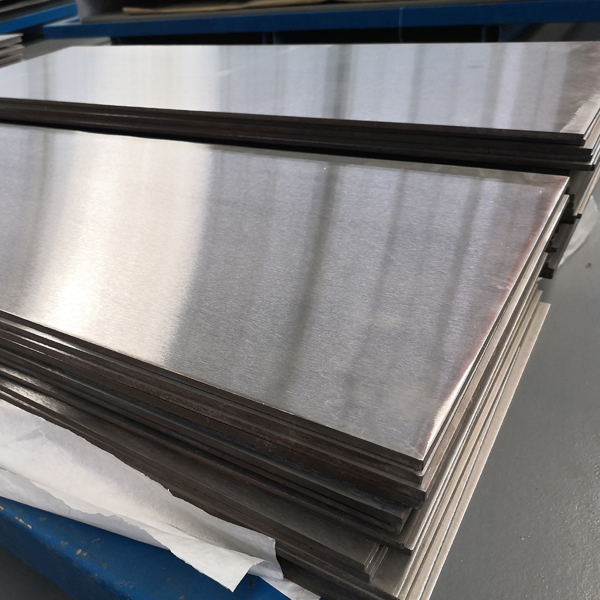
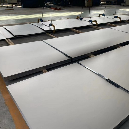
- Gr2 Titanium Sheet Price FOB Shanghai | ASTM B265 In Stock
- Titanium Price Today (Oct 26, 2026): China Market Report
- Titanium Price Today (23 Oct 2026): Plate, Tube, Rod & Wire
Contact Person: Wang Xiaoning
Tel: +86-917-355-7966
Email: sales@sxqytd.com
WhatsApp: +86 188 2967 9311
Company: Shaanxi Qianyi Tuoda Technology Co., Ltd
Address: Floor 4, Building 4, No. 188 Gaoxin Avenue, High-tech Zone, Baoji City, Shaanxi Province, China