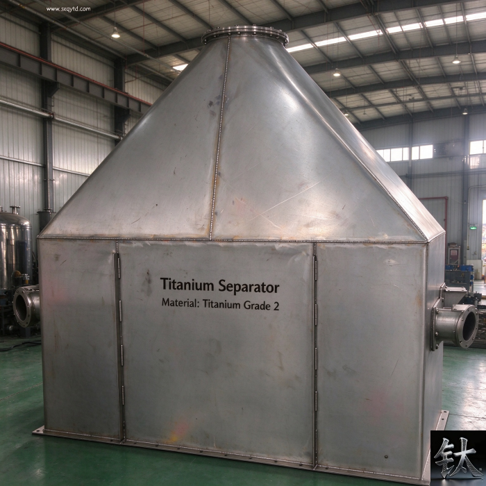
Titanium Hydrostatic Testing: Water, Chloride Limits and Drying Before Start-Up
| Спецификация | Hydrostatic test / pre-commissioning |
|---|---|
| Применимый стандарт | Titanium Gr2 / Gr7 / Gr12 vessel and tube |
| Состояние материала | Chloride limit / drying / nitrogen blanket |
| Контроль и упаковка | ASME VIII-1 UG-99 / GB/T 150 / GB 50235 / ASTM B338 |
| Справочная цена | $1000.00 – $10000.00 |
Описание продукции: A passed hydrotest is not a clean vessel: where the 25 ppm chloride rule comes from, what trapped water does, and the ITP lines for drying.
Обзор продукции
Titanium Hydrostatic Testing: Water, Chloride Limits and Drying Before Start-Up
A hydrostatic test that passes at 1.3 times the maximum allowable working pressure proves that the welds hold pressure. It says nothing about the two hundred litres of tap water still sitting in the bottom head, the jacket and the instrument leads three weeks later. Field accounts from titanium tube installers describe leaks appearing three to six months after a certificate was signed, traced not to chloride attack on a free titanium surface but to stagnant residual water concentrating under gaskets, to iron particles left by a carbon steel test pump, and to a vessel that was capped wet and parked in a laydown yard. Those are supplier field observations rather than a code clause, but they match the failure pattern that buyers keep describing to us. The expensive part of a hydrotest is not the thirty minute hold; it is the unwritten window between the test and start-up. This guide covers where the famous 25 ppm chloride figure actually comes from, why the published test pressures and hold times contradict each other, what really damages titanium after the gauge is removed, how to dry and verify dryness, how to write the inspection and test plan, and the eight ways a passed test still ends in a leak. It is deliberately not a receiving inspection article. Our three-step arrival acceptance checklist covers the certificate, dimensional and NDT checks performed when the crate arrives; our titanium storage tank guide lists hydrotest as step seven and pickling as step eight of the fabrication flow; our process equipment specification guide explains what a purchase order must state about the duty. This article deals only with the wet operations around that step seven, and with the documents that prove the vessel was dry when it left the shop.
At a Glance: What a Passed Hydrotest Does and Does Not Prove
| Item | What the buyer must know |
|---|---|
| The short answer | A hydrostatic test proves pressure integrity, nothing else. Chloride-limited test water, complete drainage, verified drying and a documented preservation state are separate line items and belong in the inspection and test plan |
| Where 25 ppm comes from | The widely quoted 25 mg/L chloride ceiling originates in piping erection codes for stainless steel, nickel and nickel alloy systems. Published industry readings note that ASTM B338 and ASME SB338 state no such requirement for titanium tube test water |
| Where the numbers disagree | Field guides specify 25 ppm for titanium pipework, 10 ppm for nuclear service and pH 6 to 8; certificate guides quote 50 ppm for austenitic stainless with some owners at 30 ppm. No single value is universal. Name the governing document and its edition |
| Test pressure conflict | ASME VIII-1 UG-99 uses 1.3 x MAWP x lowest stress ratio; GB/T 150 uses 1.25 x design pressure x stress ratio; older ASME editions used 1.5; B31.3 piping uses 1.5; EN 13480-5 and PED use 1.25. The two systems are not interchangeable |
| What actually damages titanium | Not chloride ions on a free titanium surface. It is residual water trapped in dead legs and gasket crevices that evaporates and concentrates, plus embedded free iron from carbon steel test pumps, hoses and wire brushes |
| The mixed-metal unit | A titanium shell with 316L nozzles, internals or instrument fittings still needs the chloride clause for those stainless items. Write the purchase order by material line, not by vessel |
| Drying is a hold point | Drain every low point, jacket, coil and instrument lead; purge with dry air or nitrogen; verify by dew point, boroscope or wipe record; then cap and blanket. Natural air drying is not a procedure |
| Time is the hidden variable | The 30 to 60 minute hold period is rarely the problem. The three weeks between a passed test and commissioning, with the vessel capped wet in a laydown yard, is where field reports place the damage |
| Pneumatic substitution | Allowed by engineering justification when water cannot be tolerated, commonly around 1.1 x MAWP x stress ratio under ASME UG-100, but a gas-filled vessel stores far more energy. It is a safety case, not a convenience |
| The PO line that causes trouble | “Hydrostatic test per code, water to be clean”. Clean is not a specification. Name the chloride value and its governing document, the drying method, the acceptance criterion and the witness |
| Cheapest verification | One water analysis report with date and sampling point, one signed drying log, one iron-contamination smear test after the last wet operation, and one preservation inspection record before shipment |
Read rows two, three, five and seven first. The recurring procurement error is not that a buyer forgets the pressure test; it is that the purchase order contains one short line saying hydrostatic test per code, water to be clean, and nothing at all about drainage, drying or preservation. Every numerical value in this table is orientational and carries a governing document behind it. Chloride ceilings differ between a piping erection code, a vessel code, a nuclear project specification and a field installation guide; test pressure coefficients differ between ASME, GB, EN and older editions of the same ASME section. Treat the table as a checklist of questions. The values that bind are the ones in the edition named on your own requisition, confirmed by a report issued under a method you have specified.
The “25 ppm Chloride” Clause That Does Not Mean What Buyers Think
Almost every enquiry for a titanium vessel or tube bundle arrives with a line requiring test water chloride below 25 ppm. Very few enquiries say where that number came from, which materials in the unit it protects, or who issues the water analysis. The widely quoted ceiling of 25 mg/L appears in Chinese piping erection and acceptance codes, commonly cited as GB 50235 and GB 50184, where the requirement applies to stainless steel, nickel and nickel alloy pipes and to systems connected to them. Published industry commentary on titanium tube specifically notes that ASTM B338 and ASME SB338 do not state any requirement for hydrostatic test water quality, and that the 25 ppm figure is therefore not a titanium material requirement at all. That is an industry reading of the standards rather than a quotation from them, so verify the clause in the edition you are buying under before repeating it. Our ASTM B338 tube ordering guide sets out what the tube standard does and does not cover.
Now the contradiction. Field installation guides written for titanium pipework state the opposite in practice: test water chloride at or below 25 ppm, 10 ppm for nuclear service, pH between 6 and 8, deionised water rather than tap or river water, immediate drainage and a nitrogen blow-down afterwards. Independent hydrostatic test certificate references quote a common austenitic stainless limit near 50 ppm with some owners specifying 30 ppm, and describe chloride content as a certificate field for stainless components. So the same number is presented as a stainless-only clause, a titanium field requirement, and a value that other specifications relax to 50 ppm. Three defensible positions, one purchase order line, no named document.
The practical resolution. Do not pick a winner among 10, 25, 30 and 50 ppm in a blog article. Write four things into the requisition instead: the numeric value with its unit, the specific material lines it governs, the governing document with edition year, and the party that issues the water analysis with sampling point and date. A clause that says 25 ppm per GB 50235 edition X, applied to all 316L and nickel alloy items in this unit, analysis by the fabricator laboratory and witnessed by the purchaser is enforceable. A clause that says clean water is not.
There is a second reason to be precise. A chloride ceiling is a proxy for a failure mechanism, and the mechanism that matters on a titanium shell is different from the one that matters on the 316L nozzle beside it. On austenitic stainless the concern is chloride stress corrosion cracking under tensile stress and evaporative concentration; on titanium it is the shielded stagnant crevice at elevated temperature and low pH, plus free iron. Our material upgrade ladder comparing titanium with 316L, 2205 and 254SMO explains the first mechanism in detail. Copying its clause onto a titanium line item without asking what it protects is how specifications become both expensive and ineffective.
Finally, note that the water analysis is a document, not an event. It belongs with the hydrotest certificate, the gauge calibration record, the drying log and the EN 10204 3.1 certificate chain. When a dispute arises eighteen months later, the useful evidence is a dated report tied to a heat number and a test date, not a recollection that the water looked clear. Ask for the sampling point: water drawn from the supply tank and water drawn from the vessel low point after the hold can give different answers.
Test Pressure, Hold Time and the Code Conflict Nobody Resolves on the PO
Before arguing about water, settle which code calculation produced the test pressure. Under one commonly quoted reading of ASME BPVC Section VIII Division 1 paragraph UG-99, the hydrostatic test pressure at every point of the vessel is at least 1.3 times the maximum allowable working pressure multiplied by the lowest stress ratio, that is the ratio of allowable stress at test temperature to allowable stress at design temperature taken across all pressure boundary materials. GB/T 150 uses 1.25 times the design pressure multiplied by its own stress ratio term. EN 13480-5 and the EU PED are commonly quoted at 1.25 times PS, ASME B31.3 process piping at 1.5 times design pressure, and older ASME VIII-1 editions used 1.5 before the coefficient changed. Our own titanium reactor build guide lists GB/T 150 and ASME VIII-1 as parallel build routes for the same vessel. A requisition that says simply hydrotest at 1.3 times design pressure has quietly mixed an ASME coefficient with a GB pressure basis.
The conflicts do not stop at the coefficient. Published references disagree on which UG-99 subparagraph governs a new cold vessel and which governs an in-service or re-rated one, with some placing the general formula in UG-99(b) and the calculated test pressure route in UG-99(c), and others describing UG-99(c) as the new-vessel clause and UG-99(b) as the routine re-test clause. We are not going to adjudicate that here, and neither should a purchasing department. The executable action is to require the design file to name the code, edition year, paragraph and the calculation sheet showing MAWP, design pressure, lowest stress ratio and static head correction. If two bidders quote different test pressures for the same drawing, the difference is almost always one of those inputs, not a disagreement about physics.
Static head is the input most often omitted. Test pressure is specified at the top of the vessel, but a vertical column of water adds roughly 9.81 kPa per metre. On a tall column or a 30 metre tower the pressure at the bottom head can be several bar above the top reading, so the pump set point is reduced by the head and the bottom stress is checked separately. Test weight also matters: every cubic metre of water adds about one tonne, and foundations that carry the empty vessel comfortably may not carry the flooded one. Our custom reactor and heat exchanger fabrication notes describe why the support and lift plan is reviewed before large units are filled.
Hold time is another place where a bare number misleads. ASME VIII-1 is widely described as requiring sufficient time to inspect all joints without a fixed minimum, with 30 to 60 minutes typical in practice; ASME B31.3 is quoted at a 10 minute minimum; EN 13480-5 at 30 minutes. Water temperature carries a separate constraint: several references call for the metal temperature to sit at least about 17 °C (30 °F) above the minimum design metal temperature during the test to avoid brittle fracture, with test water commonly held between 15 and 50 °C. Titanium itself retains toughness at low temperature, but a vessel with carbon steel flanges, bolting or a clad steel shell is governed by the weakest component. Ask whose MDMT was used in the calculation.
Instrumentation closes the loop. A hydrostatic test certificate is expected to record the calculated and achieved pressure, hold time, medium and temperature, gauge identification, range, accuracy class and calibration date, observations, repairs, re-test reference, and signatures including the authorised inspector where code construction applies. A gauge whose range is ten times the test pressure gives a poor-resolution reading; certification guidance commonly recommends a range around 1.5 to 4 times the test pressure with a current calibration certificate. These are the same documentary disciplines covered in our weld NDT and WPS qualification guide: a test without a traceable record is an opinion, and a re-test after a weld repair needs its own reference rather than a handwritten note on the original sheet.
Why the Water Itself Rarely Kills Titanium — and What Actually Does
Start with the counterintuitive part: titanium is not a metal that chloride water dissolves on contact. Wet chlorine, hypochlorite, seawater and chlorinated cooling water are titanium strongholds precisely because the titanium dioxide film is stable in oxidising chloride environments. Field guides that warn about test water also concede that titanium remains stable in most chloride-bearing environments, and locate the elevated risk in hot, concentrated, low pH stagnant liquid rather than in a clean flowing test fill. If the failure mechanism in your unit is free-surface chloride pitting of titanium, the grade selection was wrong long before the hydrotest; our hydrochloric acid and grade limit guide lists the services where that is genuinely true, and our Gr2 versus Gr7 seawater comparison covers the crevice threshold that Grade 7 is bought for.
Mechanism one: evaporative concentration in a shielded zone.
Residual water left in a dead leg, under a gasket, behind a support baffle, in an expanded tube-to-tubesheet joint or in a jacket does not stay at its original composition. It sits, warms, evaporates and concentrates; oxygen is depleted inside the crevice; pH can fall; the local chloride concentration can climb far above the bulk water analysis that was filed with the certificate. Industry field accounts place increased pitting and crevice risk in stagnant conditions above roughly 70 °C with high chloride and low pH, and describe leaks three to six months after otherwise successful tests. Those figures are practitioner guidance, not a codified threshold, which is exactly why the drying criterion rather than the inlet water number belongs on the hold point list. The geometry that creates the trap is discussed in our tube-to-tubesheet weld and expansion detail and in the flange, bolt and gasket three-piece selection guide.
Mechanism two: free iron from the test circuit.
A carbon steel test pump, a borrowed hose, a mild steel blind, a wire brush used to clean a nozzle face, or grinding dust from a nearby work area will deposit iron particles on a soft titanium surface. In a wet vessel those particles form microscopic galvanic cells; titanium is the noble cathode, the iron corrodes, and the pit under the rust spot keeps autocatalysing after the visible stain has been wiped away. This is the same mechanism our pickling and iron contamination guide treats in depth, including why stainless steel cleaning standards such as ASTM A967 and A380 are the wrong documents to cite on a titanium purchase order. Note the link with the titanium to steel galvanic corrosion guide: the electrical design and the surface cleanliness are two independent checks on the same wet interface. Passing one does not discharge the other.
Mechanism three: time, temperature and debris acting together.
A test fill that is drained within hours behaves very differently from one left for a fortnight while shipping documents are prepared. Weld slag, sealant fragments, cutting swarf and dirt collect in low points, hold moisture against the wall and create the shielded zone that mechanism one needs. Warm ambient conditions accelerate both evaporation and reaction. Multiply those together and a water analysis showing 20 ppm at the inlet says very little about the liquid sitting under a deposit in a blind nozzle two weeks later. This is also why the industry guidance on titanium hydrogen embrittlement and post-process verification matters here as a boundary: plain water and ordinary drying do not charge titanium with hydrogen, but the pickling, cathodic protection or repair welding that may follow the test can. Keep the two acceptance lines separate instead of writing one generic cleanliness clause.
The practical conclusion is uncomfortable for specification writers. A tighter chloride limit on the inlet water is the cheapest line to edit and one of the weaker levers. Drainability, a dedicated test circuit, elapsed time to drying, and proof that the vessel was actually dry are the levers that change outcomes. That is why the next sections are about procedure and records rather than about choosing between 10 and 50 ppm.
One Vessel, Two Chloride Rules: The Mixed-Metal Unit
Very little process equipment is entirely titanium. A Grade 2 shell may carry 316L instrument nozzles, a stainless thermowell, nickel alloy internals, carbon steel external support lugs, a clad steel tubesheet and graphite or PTFE gaskets. Each of those materials meets the same test water, and the chloride clause that is arguably unnecessary for the titanium shell is very much alive for the austenitic stainless and nickel items. Chloride stress corrosion cracking of 316L under tensile stress at elevated temperature is a well documented failure mode with published onset figures around 60 °C in neutral chlorides, falling further under acidic, oxidising or evaporative conditions. That is the mechanism the 25 ppm clause was written to suppress, and our upgrade ladder article explains why duplex or 6Mo is often the economical answer when that is the observed failure.
The specification fix. Split the requisition by material line. On the titanium lines write clean water, a defined drainage and drying procedure, an iron-contamination acceptance test after the last wet operation, and the preservation state. On the stainless steel and nickel alloy lines write the numeric chloride ceiling, its governing document and edition, the water analysis report and the post-test drying requirement. One clause for the whole vessel either over-specifies the titanium or under-specifies the stainless; usually it does both at once.
Clad and loose-lined construction adds an interface that a simple shell calculation misses. Explosion-bonded titanium-to-steel plate is a metallurgical bond with no electrolyte at the interface, so the bond itself is not a galvanic couple; the exposed cut edges, drilled holes, weld repairs and the leak detection port are where test water can reach the steel. Our solid titanium versus clad plate comparison sets out the construction choice, and the galvanic corrosion guide explains why the cut edge rather than the bonded area governs. When a clad vessel is hydrotested, the leak detection connection should be part of the drainage list, not an afterthought, and any water that enters the annulus must be removed and dried before the unit is capped.
Gaskets deserve their own line. Flexible graphite is electrically conductive and nobler than passive titanium, so in a wet joint the electrochemical check has to be run separately from the sealing check; PTFE and other non-conductive gasket systems behave differently. The flange, bolt and gasket selection guide covers pressure class, facing type and bolt grade. We are not revising its recommendation here: we are saying that a wet gasketed joint has a second independent check, and a specification that only covers the mechanical one is incomplete. The same applies to passivated Titanium Fasteners and threaded fittings, whose recesses are natural traps for test water.
Finally, some consumables in the test and inspection sequence carry chlorides or fluorides of their own. Penetrant developers, marking inks, cleaning solvents, inhibitors and temporary gasket adhesives are all worth listing. Field installation guidance for titanium explicitly calls for chloride-free penetrant materials, and fluoride-bearing products are a hard exclusion for every titanium grade. Ask for the consumable list with the inspection and test plan, not after the surfaces have been sprayed.
Drain, Dry, Verify, Blanket: Turning a Wet Test into a Clean Handover
Step one is a drainage map, not an instruction to drain.
Write down every volume that can hold water: the bottom head, each nozzle and blind flange, jacket and half-coil, internal coil and U-tube bundle, instrument impulse lines, level gauges, the tubesheet annulus, the leak detection port on clad construction, valve bodies, and any low point created by the test orientation rather than the operating orientation. Vessels are frequently tested in a different attitude from the one in which they operate, so a pocket that drains in service can be a sump during the test. Remove spool pieces and blinds where necessary, tilt or rotate small units, and use drained rather than blown-out water as the first stage. Confirming that the last low point is empty is a visual or boroscope observation with a sign-off, not a line on a generic checklist.
Step two is an active purge.
Field guidance consistently calls for dry air or nitrogen purging immediately after drainage until no free moisture remains, and rejects natural air drying as insufficient. Nitrogen has the advantage of leaving an inert atmosphere behind, which is why long shutdown preservation uses a nitrogen blanket as well. Gas quality should be specified: the same discipline that requires high-purity argon with a low dew point for GTAW shielding of titanium applies here, though the acceptance criterion is dryness rather than weld colour. Specify the supply, the flow path, the purge duration or volume, and the order in which branches are purged so that a remote dead leg is not simply bypassed.
Step three is verification, and this is the hold point most purchase orders omit.
Choose an acceptance criterion that can be recorded: a dew point reading at the outlet with the instrument and ambient conditions noted, a boroscope inspection of representative low points, a clean white wipe or swab with no moisture or residue, or a weighed desiccant comparison. Any of these can be argued about, which is why the criterion, the method and the witness must be written before the test rather than negotiated afterwards. Record the date and time of drainage completion, purge start and acceptance. The elapsed time between those three entries is the single most useful number in the whole package, because it tells a reviewer whether the unit sat wet over a weekend.
Step four is preservation.
Once dry, fit end caps or metal blinds, install desiccant where the design allows, and apply a slight positive nitrogen blanket if the lay-up period is more than a few days. Record the blanket pressure and the inspection interval, and define the maximum lay-up duration before the drying check is repeated. Industry guidance for long shutdowns explicitly recommends capping and nitrogen blanketing to keep humid air and dust out. For sea freight, the arrival acceptance article adds the complementary detail of a PE liner and desiccant inside the wooden case, because salt fog during transit is a separate exposure from the test water. Both records belong in the shipping dossier alongside the material certificate and the hydrotest certificate.
Two boundary conditions keep this section honest. First, plain water and ordinary drying do not create the hydride embrittlement described in our hydrogen embrittlement guide; do not let a generic cleanliness clause blur two different acceptance tests. Second, drying is necessary but not sufficient if the test circuit has already deposited free iron. The iron smear test after the last wet operation, described in our pickling and iron contamination guide, is a separate hold point and cannot be replaced by a dew point reading.
Sequence, Passivation and Iron Contamination: What the ITP Must Fix
Workshops do not all run the same order. A typical fabrication flow may put weld NDT first, then acid pickling and passivation, then the hydrostatic test, then final cleaning, support fitting and packing. Other published flows, including our own titanium storage tank manufacturing sequence, list the hydrostatic test as step seven and pickling and passivation as step eight. Both can be defensible depending on whether the shop wants the final surface treatment after all wet and handling operations, or wants a clean oxide film present during the fill. We are not going to declare one of our own pages wrong in public. What matters is that the sequence is fixed in the inspection and test plan, that all parties know which operation is the last wet one, and that the surface condition is re-verified after it rather than assumed from an earlier certificate.
Two independent lines of evidence. Line one: was the pressure boundary proven at the calculated test pressure with a calibrated gauge and a signed record? Line two: after the last wet operation, is the wetted titanium surface free of free iron, fluoride or chloride residue, and is the unit dry? A passed hydrotest discharges line one only. Most of the early-life failures discussed in this article happen on line two, often weeks later.
If pickling or passivation follows the hydrotest, the acid step becomes the last wet operation and inherits every obligation in the previous section: complete drainage, thorough rinsing, neutralisation where the procedure calls for it, verified drying, and an iron test afterwards. Our pickling and iron contamination guide explains why the nitric-to-hydrofluoric ratio matters more than the headline concentration, why ASTM A967 and ASTM A380 are stainless steel documents, and which titanium-appropriate specifications to cite instead. A rinse that leaves nitrate or fluoride residue in a blind nozzle recreates exactly the concentrated shielded zone described earlier, only with a more aggressive chemistry than tap water.
The test circuit itself is a contamination source that rarely appears in a drawing. Dedicate hoses, pumps, blinds, gaskets and fittings to titanium work, or specify stainless or non-metallic wetted parts; keep carbon steel tools and wire brushes away from the wetted surface; segregate the test area from grinding and steel fabrication; and prohibit chloride-bearing penetrant developers and marking materials. Where a temporary carbon steel strongback or lifting fixture is unavoidable, isolate it from the titanium with non-metallic padding. The acceptance test is cheap: a ferroxyl-type smear or portable iron ion test kit wiped on representative areas, with a recorded result and a defined action if it is positive. Make the test a witnessed hold point after the final wet step, with the NDT and qualification documentation attached to the same dossier.
One more sequencing trap: field repair. If a leak is found during the test, the repair weld introduces a new shielding requirement, a new heat tint to inspect and potentially a new local pickling step. Titanium cannot be patched with a casual field arc weld; it needs argon shielding, back purging and interpass control as set out in our GTAW shielding guide. Every repair therefore resets the drying clock and the surface acceptance checks, and the re-test needs its own certificate reference rather than a note appended to the first. Write the re-test trigger and the re-inspection scope into the ITP before the first fill.
Pneumatic Substitution, preservation and the Start-Up Hold Point
There are legitimate reasons to avoid water altogether: catalyst-sensitive interiors, cryogenic service, a lining that cannot be dried, a site with no usable water, or a schedule that cannot accommodate a drying hold. Under ASME VIII-1 the pneumatic route is commonly quoted near 1.1 times MAWP multiplied by the lowest stress ratio, with additional requirements for inspection and staged pressure increase; other codes use different coefficients and different prerequisites. Do not treat that number as universal. The more important point is physical: water is nearly incompressible, so a failure during a hydrostatic test releases comparatively little stored energy, while a gas-filled vessel at the same pressure stores a great deal. A pneumatic test is a safety case with exclusion zones, staged pressurisation, a preliminary leak check at low pressure, additional NDT and an engineering justification signed by the responsible engineer. It is never a shortcut chosen because drying is inconvenient.
Preservation between the shop test and commissioning is where most of the risk accumulates. Cap or blind every opening, keep desiccant and humidity indicator cards inside where the design permits, maintain a slight nitrogen over-pressure if specified, record the blanket pressure at defined intervals, and set a maximum lay-up period after which the drying and surface checks are repeated. For export shipments the arrival acceptance checklist notes the PE liner and desiccant inside the crate as a defence against salt fog; restate that requirement in the packing specification rather than assuming the forwarding agent will provide it. Our equipment specification guide is the right place to fix the documentation set that travels with the unit.
At site, treat the preservation state as a handover item. Review the drying log and the blanket pressure record before opening the unit; inspect representative low points and gasket faces; remove caps only when the installation sequence allows the openings to be closed again; and plan the first flush with water meeting the same specification as the shop test. If the unit has sat open in a humid or coastal yard, repeat the drying and iron checks rather than relying on a certificate issued weeks earlier. Industry maintenance notes make the same point about shutdowns: equipment often suffers more during a standing period than during operation, because residual liquid evaporates and concentrates. Start-up and shutdown procedures deserve the same chemical discipline as the original hydrotest.
Finally, confirm that the commissioning medium itself is on the approved list. A vessel bought for wet chlorine service may be flushed at start-up with a chlorinated biocide, an acid cleaner or a fluoride-bearing descalant that was never in the corrosion enquiry. The grade limit and exclusion guide lists the media that titanium cannot tolerate, and the B265 plate guide shows how to attach the medium and temperature cases to the material requisition. Add cleaning and start-up chemicals to the enquiry form. In our experience that one line prevents more disputes than any other clause in the specification.
The 14-Line ITP and Purchase Order Template Buyers Can Copy
The lines below are written as clauses rather than advice. They apply to a titanium vessel or tube bundle with mixed stainless steel or nickel items; delete the lines that do not apply and never delete the witness column. Every line that contains a number must also name the document that produced it. That single rule removes most of the ambiguity that the 25 ppm debate creates.
1. Code of construction and edition year, with the pressure-test paragraph number and the calculation sheet reference.
2. Test pressure formula and inputs
: MAWP or design pressure basis, lowest stress ratio, static head correction at the bottom head, and the resulting pump set point.
3. Pressure gauges
: identification, range (approximately 1.5 to 4 times test pressure), accuracy class, calibration certificate number and date.
4. Test medium for each material line
: define clean water by numeric limits; name the water source and the prohibition on untreated tap, river or sea water.
5. Chloride ceiling
: value with units, governing document with edition, and the exact material lines to which it applies.
6. Water analysis
: issuer, sampling point, date, chloride result, pH, conductivity, and the acceptance signature.
7. Test conditions
: water and metal temperature, MDMT margin of the weakest component, hold time with its named minimum, and inspection during hold.
8. Test circuit
: dedicated non-carbon-steel wetted parts, hoses, blinds and temporary gaskets; list of prohibited tools and consumables.
9. Consumables
: chloride-free penetrant developer, marking inks and cleaners; prohibition on fluoride-bearing products on titanium.
10. Drainage map
: every low point, jacket, coil, impulse line, annulus and leak detection port, with the method and the responsible person.
11. Drying method
: dry air or nitrogen supply, flow path, purge duration or volume, and elapsed time limit from drain complete to purge start.
12. Drying acceptance
: dew point, boroscope, wipe or desiccant criterion, with instrument, ambient conditions, date and witness hold point.
13. Surface acceptance after the last wet operation
: sequence of pickling and passivation, rinse and neutralisation, iron smear test method, result and re-test trigger after any repair weld.
14. Preservation and documentation
: end caps, desiccant, nitrogen blanket pressure and inspection interval, maximum lay-up before re-check, hydrotest certificate fields, EN 10204 3.1 certificate, NDT and PMI records, and the purchaser witness for each hold point.
Lines 5, 10, 12 and 13 do nearly all the work. Line 5 stops the mixed-method argument by tying the chloride value to a named document and named material lines. Line 10 turns drain the vessel into a list that can be audited on a drawing. Line 12 makes dryness a measured state with a witness rather than an assumption. Line 13 ensures that whichever sequence the shop uses, the surface is accepted after the last operation that could contaminate or re-wet it. The certificate and documentation guide explains how to keep the heat number chain intact across all of these records.
A practical note on supply. Tight chloride and drying clauses are easy to write and harder to fulfil on a shutdown schedule when the only available water source is a site standpipe and the unit has to ship the same afternoon. We hold roughly 800 tonnes of titanium stock in Baoji, China Titanium Valley, including about 400 tonnes of plate, and we cut to non-standard sizes, work from customer drawings, certify to ASTM, ASME and GB standards and export-pack in house. That does not remove the need for a drying hold point; it does mean the replacement tube bundle or plate can be on its way while the paperwork is being closed out. Put the required ship date on the requisition with the medium and the test clauses, not after the first delay.
Limitations and Failure Conditions: Eight Ways a Passed Hydrotest Still Fails
Read this section as a list of purchase order defects, not as a list of material defects. In every case below the titanium grade was probably correct, the weld probably passed, and the pressure gauge probably held steady. What was missing was a line in the inspection and test plan, a dated record, or a witness at the moment the vessel changed from wet to dry.
Tap water or river water used as the fill, then left in dead legs
The inlet analysis may be unremarkable and the failure still arrives. Untreated water carries chlorides, hardness, sediment and sometimes microbes into blind nozzles, jackets and instrument leads where it is not circulated and not drained. The damage is not uniform thinning; it is a local shielded cell that develops after the bulk of the water is gone. Require a defined water source, a named sampling point, a drainage map and an elapsed time limit before purge, and treat a verbal assurance that the water looked clean as a missing document rather than a minor omission.
Warm stagnant chloride water above roughly 70 °C with depressed pH
Titanium tolerates most chloride waters, but field guidance consistently places elevated pitting and crevice risk in hot, concentrated, low pH stagnant liquid. A hydrotest is normally cold, so the risk appears later: during a warm standing period, a steam-out, or a first batch that runs hotter than the design case while residual water is still trapped under a gasket or deposit. Ask for the maximum metal temperature across start-up, cleaning and shutdown, not just the design temperature, and specify a palladium-bearing grade at crevice-prone locations where the duty is genuinely hot and stagnant.
A vessel capped wet and stored for weeks before commissioning
Test certificates record the hold period, not the calendar. The common field account is a unit that passes on a Friday, sits capped and wet through a weekend and a shipping delay, and is commissioned three weeks later with no drying log at all. Time converts a small residue into a concentrated one. Set an elapsed time limit from drain complete to purge start, require dated and timed entries for drainage, purge and acceptance, and repeat the drying and surface checks whenever the documented lay-up limit is exceeded before start-up.
Carbon steel test pumps, hoses, blinds and wire brushes in the circuit
Free iron embedded in a soft titanium surface creates a microscopic galvanic cell in the presence of moisture. Titanium is the cathode, so the visible rust is the iron dissolving, while the pit underneath keeps autocatalysing after the stain disappears. The sources are mundane: a borrowed carbon steel pump, a mild steel blind, a wire brush on a nozzle face, grinding dust drifting from an adjacent bay. Dedicate the test circuit to titanium work, segregate the area, and make an iron smear test after the last wet operation a witnessed hold point with a defined corrective action.
Chlorinated disinfectants, hypochlorite flushes and chloride-bearing PT developers
Consumables are frequently outside the material specification. A chlorinated biocide used for a first flush, a hypochlorite disinfectant, a chloride-bearing penetrant developer or a marking ink can put more aggressive chemistry onto the surface than the test water ever did. Fluoride-bearing cleaners and descalants are a hard exclusion for all titanium grades. Ask for the full chemical inventory including cleaning, start-up and maintenance products, put a prohibition on unapproved chloride and fluoride products into both the purchase order and the site procedure, and require a rinse and drying record after any approved chemical contact.
Mixed 316L or nickel alloy nozzles and internals inside a titanium shell
This is the specification error that a single vessel-wide chloride clause cannot fix. The titanium shell does not need the same protection as the 316L instrument nozzle beside it, and the austenitic item is the one exposed to chloride stress corrosion cracking under tensile stress and evaporative concentration. Split the requisition by material line, apply the numeric ceiling and its governing document to the stainless and nickel items, and apply the drainage, drying and iron acceptance criteria to all wetted surfaces. A clause written for the whole vessel usually over-specifies one family and under-specifies the other.
Pneumatic substitution without a stored-energy and fracture review
Replacing water with gas is sometimes correct and sometimes chosen simply to avoid the drying hold. Gas at test pressure stores far more energy than a nearly incompressible liquid, so a failure is a safety event rather than a leak. Published coefficients and prerequisites differ by code and edition, and a figure quoted without its paragraph is not a procedure. Require an engineering justification, staged pressurisation, a low-pressure leak check, exclusion zones, additional NDT and the responsible engineer signature. Where water is permissible, the safer route is to keep water and specify the drying properly.
Insulation and cladding fitted over a wet or chloride-bearing surface
Insulation is installed late, often after the hydrotest records are closed, and it creates a new shielded zone against the shell. If the surface is still damp, carries chloride residue, or the cladding allows rain ingress during lay-up, the outside of the vessel develops the same concentration cell as the inside. Insulation materials can themselves contribute chlorides. Add a surface dryness and cleanliness check before insulation, specify low-chloride insulation for the duty, seal cladding penetrations, and include the insulated annulus in the preservation inspection plan while the unit waits for start-up.
Summary: Choose a Water Test if, Choose a Pneumatic Test if, Escalate if
Choose a conventional hydrostatic test with a full drying hold point if:
- The design is a pressure vessel under ASME VIII-1 or GB/T 150 and the code route expects a liquid fill.
- Suitable low-chloride water and a dedicated non-carbon-steel test circuit are available at the shop.
- The drainage map covers every jacket, coil, impulse line, annulus and leak detection port.
- A dry air or nitrogen supply, a measurable dryness criterion and a purchaser witness can be scheduled.
- The unit will ship or start up within the documented preservation window, or the drying check will be repeated.
Choose a justified pneumatic test if:
- The interior is catalyst-sensitive, cryogenic, lined, or otherwise cannot tolerate residual water.
- An engineer has signed the stored-energy, fracture and exclusion-zone assessment under the governing code edition.
- Additional NDT, staged pressurisation and a low-pressure leak check are in the procedure and are witnessed.
- The coefficient, paragraph and prerequisites come from the project design code rather than from a general article.
Escalate to a corrosion or materials review if:
- The unit contains mixed titanium, stainless and nickel items and the enquiry carries one vessel-wide chloride clause.
- Any fluoride-bearing, chlorinated or acidic cleaning chemical appears in the start-up or maintenance inventory.
- The observed failure is free-surface pitting or crevice attack of titanium at the design temperature, which is a grade selection issue, not a test issue.
- The vessel has already sat wet beyond the preservation window and no drying log exists.
The whole subject reduces to one sentence: a hydrostatic test proves the pressure boundary; a signed drying and surface record proves the vessel was handed over clean. When you send an enquiry, the six most useful inputs are the construction code with edition, the complete material list by component, the full chemical inventory including cleaning and start-up chemicals, the maximum metal temperature across all cases, the drainage geometry with its dead legs and jackets, and the required ship date. Those six lines resolve the chloride argument before it starts and remove most of the round trips that delay shutdown orders. We hold roughly 800 tonnes of titanium stock in Baoji (China Titanium Valley), including about 400 tonnes of plate, cut to non-standard sizes, work from customer drawings, certify to ASTM / ASME / GB, can read a drawing rather than only a size list, export-pack in house, and dispatch confirmed in-stock orders the same day. Send us the drawing, the medium and the intended test clause and we will tell you honestly which hold points your plan is missing. Request a quote →
Frequently Asked Questions
Does ASTM B338 require chloride-limited water for the hydrostatic test of titanium tube?
Published industry commentary notes that ASTM B338 and ASME SB338 do not specify a requirement for hydrostatic test water quality, and that the widely quoted 25 mg/L chloride ceiling comes from piping erection codes written for stainless steel, nickel and nickel alloy systems. That is an industry reading rather than a quotation from the standard, so verify the clause in the edition named on your order. In practice many titanium field guides still require 25 ppm, or 10 ppm for nuclear service, so the safe route is to name the value, the governing document and the material lines it covers.
What chloride limit should I write on a titanium vessel purchase order?
There is no single correct number. Field guides give 25 ppm with pH 6 to 8 and 10 ppm for nuclear work, certificate references quote around 50 ppm for austenitic stainless with some owners at 30 ppm, and titanium tube standards are reported to state no water limit at all. Write the numeric value with units, name the governing document and edition, list the exact material lines it applies to, and require a dated water analysis with a defined sampling point. If the unit contains 316L or nickel items, keep the clause for those lines regardless of what you decide about the titanium shell.
Is 1.3 or 1.25 the correct hydrostatic test pressure for my vessel?
It depends on the code of construction. ASME BPVC Section VIII Division 1 UG-99 is commonly quoted at 1.3 times MAWP multiplied by the lowest stress ratio, GB/T 150 at 1.25 times design pressure with its own stress ratio, EN 13480-5 and the PED at 1.25 times PS, and ASME B31.3 piping at 1.5 times design pressure. Older ASME VIII-1 editions used 1.5. Mixing an ASME coefficient with a GB pressure basis is a common drawing error. Require the calculation sheet with the code, edition, paragraph, stress ratio and static head correction, and compare bidders on that sheet rather than on a bare multiplier.
Can we simply let the vessel air-dry after the test?
No. Field installation guidance for titanium calls for immediate and complete drainage followed by an active purge with dry air or nitrogen until no free moisture remains, and describes natural air drying as inadequate. The reason is that water trapped in a dead leg, jacket, coil or gasket crevice evaporates and concentrates rather than disappearing. Specify a drainage map, a purge supply and path, an elapsed time limit, and a measurable acceptance criterion such as a dew point reading, boroscope inspection or wipe record with a witness.
Why can a vessel that passed its hydrotest leak three to six months later?
Field accounts of titanium tube installations attribute these leaks to concentrated residual chloride in trapped water at joints and flange sealing faces, and to free iron left on the surface by carbon steel test equipment. The test itself proved the pressure boundary; the damage developed during the wet standing period afterwards. These are practitioner observations, not a code-defined incubation time, so treat the interval as a warning rather than a prediction. A signed drying log, an iron smear test after the last wet operation and a preservation record are the evidence that closes the gap.
Can a pneumatic test replace the hydrostatic test to avoid water altogether?
It can when water is genuinely unacceptable and the governing code permits substitution, but it is a safety case rather than a convenience. Published ASME VIII-1 guidance places the pneumatic route near 1.1 times MAWP multiplied by the lowest stress ratio with staged pressurisation, a low-pressure leak check and additional inspection; other codes differ. A gas-filled vessel stores far more energy than a liquid-filled one, so exclusion zones, fracture review, extra NDT and an engineer signature are required. Name the paragraph and edition rather than copying a coefficient.
Does the order of the hydrotest and pickling or passivation matter?
It matters that the order is fixed in the inspection and test plan and that the surface is accepted after the last wet operation, whichever step that is. Some shops pickle before the fill so the clean oxide film is present during the test; other published fabrication flows list the hydrotest first and pickling afterwards so the final surface treatment follows all handling. Both routes can work. What fails is an unstated sequence, an acid rinse left in a blind nozzle, a repair weld that silently resets the surface condition, or a re-test recorded only as a note on the original certificate.
Опишите ваши требования — марка, размер и количество. Ответим в течение 24 часов.
Предпочитаете чат? WhatsApp +86 188 2967 9311 или напишите на sales@sxqytd.com.
- Что такое титан фланец| ASME B16.5 ASTM B381 Gr2 Gr5 титановые флажк
- ASME B16.5 титановая флажка класса 2 DN100-DN600 Класс 150/300 FOB
- Gr2 Titanium Sheet Price FOB Shanghai | ASTM B265 In Stock
- Titanium Price Today (26 октября 2026 г.): отчет о рынке Китая
- Цена на титан сегодня (23 октября 2026 г.): пластина, трубка, стерже
Контактное лицо: Wang Xiaoning
Телефон: +86-917-355-7966
Эл. почта: sales@sxqytd.com
WhatsApp: +86 188 2967 9311
Компания: Shaanxi Qianyi Tuoda Technology Co., Ltd
Адрес: Floor 4, Building 4, No. 188 Gaoxin Avenue, High-tech Zone, Baoji City, Shaanxi Province, China