Titanium Coil and Strip: Slit Width, Uncoiling and the Fit-Up Dimension Chain
| Спецификация | Nominal size: 0.03 to 3.0 mm thickness and 10 to 600 mm slit width as published on our coil and strip specification page |
|---|---|
| Применимый стандарт | Mating part: uncoiler mandrel and coil car, leveler roll gap, press feeder and the die strip layout |
| Состояние материала | Governing drawing: press or tooling drawing revision, ASTM B265 edition named in the PO and the slitting order |
| Контроль и упаковка | Tolerance basis: slit width and camber, edge burr height, across-width gauge map, coil ID and coil mass, leveler residual stress and heat-to-coil traceability |
| Справочная цена | $8.90 – $12.00 |
Описание продукции: A slit width is a slitting result, not a rolling width. Coil ID, edge burr, across-width gauge and leveler stress decide whether strip feeds the press.
Обзор продукции
Titanium Coil and Strip: Slit Width, Uncoiling and the Fit-Up Dimension Chain
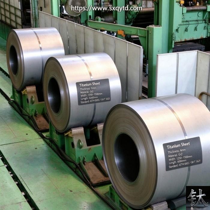
A titanium coil strip ordered at 0.8 mm by 200 mm is a slitting result, not a rolling width: the 200 mm was produced by a rotary knife pass on a wider mother coil, and the usable width that a press feeder will accept is smaller than 200 mm once both slit edges and the camber drift over the feed length are counted. Two independent interfaces fail before that strip ever reaches a die, because the coil inner diameter and the coil mass must first match the uncoiler mandrel and the coil car. Our coil and strip specification page, our bright surface coil strip page and our wire receiving and identification guide settle what coil strip is and which standard and surface condition to buy; this article starts where they stop, at the slit width and coil geometry that actually feed the press.
At a Glance: Eight Decisions Between a Slit Coil and a Feeding Coil
| Item | What the decision turns on |
|---|---|
| The short answer | A slit width is a result of the slitting pass, not the rolling width; a nominal width is not a feed fit |
| The governing identity | Feedable strip width equals the slit width, and the usable width equals that slit width minus twice the edge condition allowance and the camber drift over the feed length |
| The first interface | Coil inner diameter and coil mass must match the uncoiler mandrel, coil car and brake before any width is discussed |
| The edge trap | Slit edge burr and rollover set the die clearance and can jam a high speed feeder even when the width measures inside tolerance |
| The gauge trap | Thickness crown and wedge across the width survive slitting, so one centre reading does not describe the strip the die sees |
| The stress trap | Uncoiling and leveling release residual stress, so strip flatness and springback at the die are not the same as on the coil |
| The identity trap | After the coil is unwound and cut to length, the heat number travels on a tag, not on the metal |
| The one document | A 14-line Coil Strip Slitting and Uncoiling Fit-Up and Dimension Chain Verification Sheet: check, basis, method, criterion, who signs |
Rows two and four hide most of the rework, and our ASTM B265 sheet strip and plate page sets the product form. Our coil selection guide gives the buying context and our EN 10204 3.1 mill certificate page shows the form of a traceable thickness record. A stockholder can certify a heat number and a delivered gauge; it cannot certify the usable width at your feeder pitch without measuring the slit edge and the camber on that coil.
The Slit-Width Trap: A Slit Width Is a Result, Not a Rolling Width
A mother coil leaves the rolling mill at its rolled width. The narrow strip a buyer orders is produced by a slitting line that cuts that mother coil into several lanes with rotary knives, then rewinds each lane. The ordered width is therefore the outcome of a knife setting, a knife clearance and a rewind tension, not a dimension guaranteed by the rolling mill.
Three geometric consequences follow. First, the slit width has a tolerance band set by the slitting order, and the die layout must be built around the worst case rather than the nominal. Second, each slit edge carries a burr and a rollover, so two edges consume usable width even when a micrometer reads the nominal figure across the full strip.
A slit width is a process result with two edges. Name the slitting order, the knife condition and the edge allowance before you treat that width as a die input.
The trap closes when a tooling engineer writes the nominal 200 mm into a strip layout with no edge allowance and no camber budget. At the feeder, the strip then rubs the guide, the pitch drifts and the part is stamped off centre. Confirm the slitting order revision, the knife setup record and the number of lanes taken from the mother coil, because lane position decides the across-width gauge that strip inherited.
Where the Tolerance Goes: Edge Burr, Camber and the Across-Width Gauge Chain
The usable width at the die is one identity, not a tolerance. It equals the measured slit width, minus twice the edge condition allowance, minus the camber drift accumulated over the feed length between the uncoiler and the first die station. Camber is the deviation of the strip edge from a straight line over a stated length, and it acts like a slow steering input: the further the strip travels through the feeder, the more the edge walks sideways.
The across-width gauge chain is separate and equally decisive. A mother coil is rarely flat in section; it carries crown, wedge and local high spots from the rolling pass. A single ultrasonic reading at the strip centre does not describe the two edges the die actually forms.
Edge condition is the third term. A slit edge carries a burr, a rollover and a work-hardened lip. At high speed feeding that lip scrapes the guide, sheds particles into the die and can start a tear that propagates into the part.
The Dimension Nobody Measures: Coil ID, Coil Mass and the Uncoiler Mandrel
Before width matters, the coil has to go on the machine. Coil inner diameter, outer diameter and coil mass decide whether the mandrel can expand into the core, whether the coil car can lift the load and whether the brake can hold tension without collapsing the inner wraps. A coil that fits the mandrel but exceeds the car rating is a handling reject; a coil that fits the car but has an oversized inner diameter will slip on the mandrel and wander during feeding.
The core itself is a fit interface. A damaged or oval core, a telescoped coil or a soft inner wrap produces a varying effective radius, so the feeder sees a changing strip length per mandrel revolution and the pitch drifts even when the servo is correct. Measure the inner diameter at several angular positions, check the coil for telescoping and record the outer diameter and mass against the line capacity before release.
Coil geometry is the first fit-up gate. A strip that cannot be held on the mandrel cannot be fed to a die, whatever its width measures.
A second, quieter failure is the change of coil in the middle of a production run. A replacement coil from another heat or another slitting setup resets width, gauge, camber and residual stress at once. Re-run the measurement grid, re-set the feeder guides and re-issue the verification sheet before restarting.
Three Fit-Up Interfaces: Uncoiler, Leveler and the Press Feed
The uncoiler sets the tension baseline
Back tension at the uncoiler is the first geometric input to flatness. Too little tension lets the strip sag between the coil and the leveler; too much tension stretches the thin gauge and changes the effective pitch. Brake setting, mandrel expansion and coil mass all enter here.
The leveler sets the residual stress state
A coil stores curvature from being wound. Leveling bends the strip alternately to yield it past that curvature, and the roll gap, roll diameter and number of work rolls decide how much of the original stress is removed. Titanium has a lower elastic modulus than steel and a pronounced springback, so a leveler setup copied from a steel line commonly leaves either coil set or a reverse bow.
The press feed closes the dimension chain
At the feeder the strip width, the guide clearance, the feed pitch and the die pilot meet. The pilot locates the strip, so a width on the high side of the band jams the guide while a width on the low side lets the strip wander between pilots. Camber accumulated over the free length between the leveler and the feeder adds a sideways drift that no width measurement at the coil predicts.
When the Published Slit and Camber Numbers Disagree: Publish the Conflict, Not One Value
Ask several sources for a slit width tolerance, a camber limit, a burr height or a leveler roll gap and you get a spread, not one table. Slitting guides, tooling notes, material supplier pages and our own specification pages use different gauge bands, knife conditions, reference lengths and definitions. Presenting any one figure as the correct value would be false precision.
| Quantity | Figures in conflict | Why they disagree | What to confirm |
|---|---|---|---|
| Slit width tolerance | One slitting guide quotes a fixed plus and minus band for narrow lanes; another scales the band with strip width; a tooling note quotes a band tied to the number of lanes cut from the mother coil | Different gauge, knife clearance, rewind tension and lane count | Slitting order revision, knife setup record and measured width at head, middle and tail |
| Camber or edge straightness | One guide quotes a maximum deviation over a two metre reference length; another quotes millimetres per metre; a third quotes a percentage of strip width | Different reference lengths and whether the value is measured on the coil or after leveling | Named reference length, measuring base and the free length between leveler and feeder |
| Slit edge burr height | One tooling note expresses burr as a fraction of gauge; a slitting guide quotes an absolute maximum; a third quotes no burr limit and relies on a downstream deburring pass | Different gauge, knife sharpness and whether the burr is removed before feeding | Tooling drawing clause, knife change record and a measured edge profile |
| Coil inner diameter | Supplier pages list several standard core sizes; a line manual names one mandrel range; a rewinding note allows a tolerance on core ovality | Different rewinding lines, core materials and mandrel designs | Uncoiler manual, measured core at several angles and the coil car rating |
| Across-width gauge variation | Mill notes describe crown as a percentage of nominal gauge; others quote an absolute edge-to-centre difference; a buyer guide quotes no crown figure at all | Different rolling passes, mother coil widths and lane positions | Mother coil lane position and a mapped gauge survey at edges and centre |
| Leveler roll gap and passes | One guide recommends a gap near gauge; another recommends an interference based on yield strength; a third names a minimum number of bending reversals | Different alloys, tempers, roll diameters and flatness criteria | Line setup sheet, measured flatness after leveling and the springback result at the die |
Our B265 specification guide and our B265 plate sheet and strip page show why the edition must be named, and our mill certificate page shows the delivered gauge that anchors the chain. A chart is a buying aid; the measured width map, the edge profile and the signed verification sheet are the tie breakers. Chapter ten gives six actions that settle the numbers.
Two Independent Check Lines: Feed Geometry Here, Coil Identity There
Whether a delivered coil is settled by mass or by area, and whether its heat number survives the slitting and rewinding steps, are commercial and traceability questions, not feed-geometry questions. They belong to the receiving and identification line that our receiving weight guide, our plate weight calculator and our receiving and identification guide already cover. We do not restate that line here.
Keep the two records separate. The receiving file holds the purchase order, the mill certificate, the slitting order, the mass or area record and the heat-to-coil tag. The feed file holds the tooling drawing revision, the measured coil geometry, the width map and edge profile, the across-width gauge survey, the leveler setup, the flatness and camber readings at the feeder and the signed 14-line sheet.
Limitations and Failure Conditions: Eight Coil Strip Fit-Up Rejection Triggers
[Geometry] Trigger 1 - Die layout built on the nominal slit width with no edge allowance
Recalculate the usable width from the chain: measured slit width minus twice the edge condition allowance minus the camber drift over the free feed length. A layout that equates the ordered width with the usable width omits two edges and the drift. Judge against the approved calculation and the tooling drawing revision.
[Geometry] Trigger 2 - Coil inner diameter, outer diameter or mass outside the uncoiler and coil car rating
Measure the core at several angular positions, check ovality and telescoping, and confirm the outer diameter and mass against the line capacity before release. A coil that slips on the mandrel produces a drifting pitch no servo setting can correct. Our coil selection guide gives the buying baseline.
[Geometry] Trigger 3 - Across-width gauge crown and wedge ignored because a centre reading passed
Map the gauge at both edges and the centre at the head, middle and tail, then check the local minima against the die clearance and forming allowance. Slitting does not remove the crown inherited from the mother coil. Our B265 plate sheet and strip page names the edition.
[Fit] Trigger 4 - Slit edge burr and rollover jamming the feeder guide or shedding particles into the die
Measure the edge profile, confirm the knife change record and check the burr against the tooling drawing clause. A burr that measures inside a generic table can still scrape the guide at high feed speed. Our surface cleaning guide covers the condition of the edge.
[Fit] Trigger 5 - Camber drift over the free length between leveler and feeder pushing the strip off the pilot
Measure straightness over the named reference length after leveling, then check the strip position at the feeder rather than at the coil. A slow edge walk widens the effective width and breaks pilot location. Our coil selection guide gives the form context.
[Fit] Trigger 6 - Leveler setup copied from a steel line leaving coil set or reverse bow in titanium strip
Confirm the roll gap, roll diameter and number of bending reversals against the strip condition and the measured springback at the die. Titanium does not respond to a steel leveler setup in the same way. Our hot and cold rolled Grade 5 plate page gives the processing context.
[Process] Trigger 7 - Replacement coil from another heat or slitting setup running on the previous feeder setup
Any change of heat, mother coil, knife setup or slitting order revision resets width, gauge, camber and residual stress at once. Re-run the measurement grid, re-set the guides and re-issue the 14-line sheet before restarting. Our zero cutting page covers short and non-standard coils.
[Process] Trigger 8 - No width map, no edge profile, no signed verification sheet or lost heat-to-coil traceability
Reconcile every slit coil, leveled strip and stamped part against the heat number, the slitting order revision, the tooling drawing revision and the signed sheet. A coil whose width and gauge maps cannot be rebuilt is a reject regardless of a clean mill certificate. Our EN 10204 3.1 certificate page shows what the mill record proves.
The 14-Line Coil Strip Slitting and Uncoiling Fit-Up and Dimension Chain Verification Sheet
| # | Fit-up check | Basis drawing or standard edition | Measurement method | Acceptance criterion | Who signs |
|---|---|---|---|---|---|
| 1 | Standard edition, grade and surface condition named | Purchase order and MTC | Document review | One designation with revision | Buyer QA |
| 2 | Slitting order revision and knife setup record named | Slitting order and line log | Document review | One revision, knife condition logged | Slitting supervisor |
| 3 | Coil inner diameter measured at several angles | Uncoiler manual and coil drawing | Caliper or bore gauge at mapped angles | Inside mandrel range, ovality logged | Press setup lead |
| 4 | Coil outer diameter and mass checked against car and brake | Line capacity sheet | Weighbridge and diameter survey | Inside coil car and brake rating | Press setup lead |
| 5 | Mother coil lane position recorded | Slitting order and mill record | Document review and lane map | Lane position tied to this coil | Slitting supervisor |
| 6 | Slit width measured at head, middle and tail | Slitting order and drawing revision | Calibrated caliper or optical gauge at mapped stations | All stations inside band, minima logged | Tooling inspector |
| 7 | Slit edge burr and rollover profile measured | Tooling drawing edge clause | Edge profile gauge or microscope | Burr and rollover inside criterion | Tooling inspector |
| 8 | Across-width gauge crown and wedge mapped | MTC and measurement plan | Ultrasonic or micrometer survey at edges and centre | Local minima logged, inside forming allowance | Tooling inspector |
| 9 | Camber measured over the named reference length | Tooling drawing straightness clause | Straightedge and feeler after leveling | Drift inside the free feed length budget | Press setup lead |
| 10 | Usable width at the feeder published and signed | Tooling drawing and dimension chain | Independent recalculation from measured width | Usable width covers pilot and guide clearance | Tooling engineer |
| 11 | Leveler roll gap and bending reversals recorded | Line setup sheet and strip condition | Setup review plus flatness check after last pass | No coil set or reverse bow at the die | Press setup lead |
| 12 | Feed pitch and pilot location verified on a first article | Tooling drawing revision | First article measurement at the die | Pitch inside band, pilot locates strip | Tooling inspector |
| 13 | Heat-to-coil and coil-to-part traceability reconciled | MTC, slitting order and production record | Identity review across coil changes | One heat and one setup per released lot | Quality lead |
| 14 | Cumulative feed fit and signed verification sheet | General arrangement and dimension chain | Measure offset at the feeder and reconcile records | Offset inside criterion, hold released | Quality lead and buyer |
Line six is often answered with one width reading instead of a head, middle and tail survey, line eight with a centre gauge reading instead of an edge-to-centre map, line nine with a straightness figure measured on the coil instead of after leveling, and line ten with the nominal width rather than the usable width. Our mill certificate page and our receiving weight guide separate material and settlement evidence from feed work. Our receiving and identification guide covers the paperwork that travels with an unwound coil, and our equipment layup guide shows the downstream cost of an undocumented handover.
Six Verification Actions When Slit Tolerance and Residual Stress Figures Conflict
- Require every acceptance value to carry its document, revision and clause. Name the ASTM B265 or ASME SB-265 edition, the slitting order revision, the tooling drawing revision and the surface condition before quoting any width band. Our B265 specification guide is a product reference, not the governing clause, and our cut to size ready stock page shows the forms we hold.
- State the sample condition and measuring method: as slit, deburred or leveled, and the width from a head, middle and tail survey rather than the nominal figure. Our coil selection guide gives the buying baseline.
- Publish the feed chain before cutting tooling: measured slit width, twice the edge allowance, the camber drift over the free feed length and the usable width at the pilot. A calculation is a prediction; the measured width map at the feeder is the record. Our plate weight calculator is a mass tool, not a layout tool.
- Name who reviews the conflict: buyer quality, tooling engineer, slitting supervisor and press setup lead, with authority to accept or hold. Our WPS qualification guide shows that qualification is a signed decision.
- Keep records independent with their own dates: purchase order and mill certificate, slitting order and knife setup, coil geometry survey, width and edge map, across-width gauge survey, leveler setup, feeder readings and the signed verification sheet. Our EN 10204 3.1 certificate page covers what the mill record proves.
- Use trigger-based re-verification: any coil change, heat change, knife change, re-leveling, slitting order revision or opened hold forces reassessment. Our equipment layup guide shows the downstream cost of an undocumented handover.
Most of these cost nothing at planning and a great deal after a die is built and a production run is scrapped. Ask for the slitting order clause, the coil geometry survey, the width and edge map, the across-width gauge survey and the signed verification sheet for the same coil. We are a stockholder, not the author of your tooling drawing; where figures come from published guides we label them, and where they disagree we give the disagreement and the action.
Summary: Choose a Width-Only Layout if, Choose a Re-Measured Feed Chain if
Choose X if: a nominal-width layout with a signed verification sheet
- The purchase order names the standard edition, the surface condition, the slitting order revision and the tooling drawing revision, and the usable width and feeder pitch are stated.
- A head, middle and tail width survey plus an edge profile set the usable width, and the camber drift is budgeted over the free feed length.
- Coil inner diameter, outer diameter and mass are checked against the uncoiler mandrel, coil car and brake before the coil is released.
- An across-width gauge map and a leveler flatness check are signed per line before the first production part is stamped.
Escalate to a fit-up hold or a tooling review if:
- A clean mill certificate or a clean weighbridge ticket is the only feed evidence offered; our bright surface coil strip page describes the condition but not the feed geometry.
- The die layout was built from the nominal slit width with no edge allowance and no camber budget.
- Published slit tolerances, camber limits or burr heights disagree and no one has named the governing slitting order.
- The coil geometry does not match the uncoiler mandrel or the coil car rating.
- The width map, the across-width gauge survey, the leveler setup or a signed verification sheet is missing.
Choose Y if: a re-measured feed chain and a new setup
- The coil was substituted by another heat, another mother coil or another slitting setup; settle the dimension chain again before restarting. Our zero cutting page covers the non-standard sizes that make this common.
- The design controls a pilot-located strip width, so an edge allowance cannot be absorbed. Our process equipment buyers guide gives the equipment context.
- The buyer cannot produce a width map, an edge profile or a signed verification sheet; set up the line records first.
- Mass-versus-area settlement or heat identification is in dispute; keep that on the receiving line and read our receiving weight guide while the feed line stays independent.
The whole subject reduces to one sentence: a nominal width is not a feed fit, because the slitting order tells you what was cut while the tolerance chain tells you whether the leveled strip will run through the die. When you enquire, send the surface condition, the standard edition, the slitting order revision, the tooling drawing revision, the coil inner diameter and mass, and the measured slit width and gauge map. We are a Baoji China Titanium Valley titanium stockholder with roughly 800 tonnes in stock, about 400 tonnes of it in plate and coil forms; we cut to non-standard and small-batch sizes, work from customer drawings, read and certify to ASTM, ASME and GB standards, export-pack in house, and dispatch confirmed in-stock orders the same day. Send us the tooling drawing and the coil geometry, and we will tell you what we can ship and which decisions belong with your team. Request a quote
Frequently Asked Questions
Is the slit width on the order the same as the usable width at the die?
No. The ordered slit width is a result of the slitting pass and still contains two slit edges. The usable width equals the measured slit width minus twice the edge condition allowance, minus the camber drift accumulated over the free feed length between the leveler and the feeder.
Does a clean mill certificate prove that a coil will feed the press?
No. A mill certificate proves the heat, the grade and the delivered gauge of the mother coil; it does not prove the slit width, the edge burr, the camber or the flatness after leveling on your line. Those are produced by slitting, rewinding and leveling, which happen after the certificate was issued.
Why does a coil that fits the mandrel still produce a drifting feed pitch?
Because the effective radius changes. A damaged or oval core, a telescoped coil or soft inner wraps produce a varying radius, so the strip length delivered per mandrel revolution changes and the pitch drifts even with a correct servo. Back tension, mandrel expansion and coil mass also enter the tension baseline.
How much slit edge burr is acceptable for high speed feeding?
There is no single published value that governs. One tooling note expresses burr as a fraction of gauge, a slitting guide quotes an absolute maximum, and a third quotes no limit and relies on a downstream deburring pass. The figures disagree because gauge, knife sharpness and deburring practice differ.
Must the feeder be re-set when a replacement coil is loaded?
Yes. A coil from another heat, another mother coil or another slitting setup resets width, gauge, camber and residual stress at once. Re-run the head, middle and tail width survey, re-map the across-width gauge, re-measure the edge profile, re-set the guides and re-issue the 14-line verification sheet before restarting.
Who signs the across-width gauge map and the leveler setup?
The tooling inspector signs the across-width gauge map against the measurement plan and the tooling drawing revision, and the press setup lead signs the leveler roll gap and bending reversals against the line setup sheet and the measured flatness after the last pass. A single centre reading is not a map, because the mother coil crown and wedge survive slitting and the outer lanes differ from the centre lanes. Published crown figures disagree, so name the governing edition and confirm the local minima.
Is the feed fit-up check the same as the receiving and identification check?
No. They are two independent check lines at two gates. The receiving line decides what was bought and paid for, and keeps the heat number on the coil tag after unwinding, using the purchase order, the mill certificate, the mass or area record and the slitting order.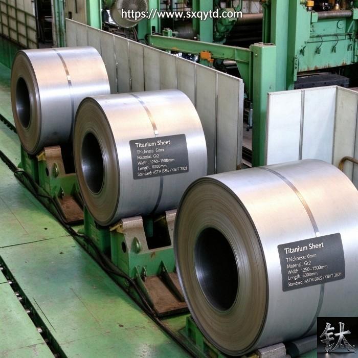
Request a Quote for Titanium, Nickel or Zirconium
Tell us what you need. Send the points below and we reply with live stock status, price and lead time — usually the same day.
Send us these 6 points (or just attach your drawing / old supplier spec)
| 1 | Material grade — Gr2 / Gr5 / Gr7 / Gr12, Ni200 / Ni201 / Monel 400, Zr702… |
| 2 | Form — plate / tube / bar / wire / fitting / flange / fastener / equipment |
| 3 | Size & tolerance — thickness×width×length / OD×WT / diameter |
| 4 | Quantity — kg / pcs / m (small batch and non-standard sizes welcome) |
| 5 | Standard — ASTM B265 / B338 / B348, ASME B16.5, EN 1092-1… |
| 6 | Application & destination — helps us pick the right grade and certifications |
Not sure how to fill this? Send your drawing or an old supplier's specification sheet — we will break it down for you.
Reach us directly
Email: [email protected]
WhatsApp / WeChat:+8618829679311 leave your number on the form
Or use the inquiry form on this page — attach your drawing and we will respond within one business day.
Why buyers come to us
Stock holder in Baoji Titanium Valley with ~800 t inventory · cut-to-size and small batch · drawing-based machining for non-standard parts · we read ASTM / ASME / GB specs · export experience · same-day response on quotes.
Опишите ваши требования — марка, размер и количество. Ответим в течение 24 часов.
Предпочитаете чат? WhatsApp +86 188 2967 9311 или напишите на [email protected].
- Titanium Price Today (9 Nov 2026): Plate, Tube, Rod & Wire
- Что такое титан фланец| ASME B16.5 ASTM B381 Gr2 Gr5 титановые флажк
- ASME B16.5 титановая флажка класса 2 DN100-DN600 Класс 150/300 FOB
- Gr2 Titanium Sheet Price FOB Shanghai | ASTM B265 In Stock
- Titanium Price Today (26 октября 2026 г.): отчет о рынке Китая
Контактное лицо: Wang Xiaoning
Телефон: +86-917-355-7966
Эл. почта: [email protected]
WhatsApp: +86 188 2967 9311
Компания: Shaanxi Qianyi Tuoda Technology Co., Ltd
Адрес: Floor 4, Building 4, No. 188 Gaoxin Avenue, High-tech Zone, Baoji City, Shaanxi Province, China