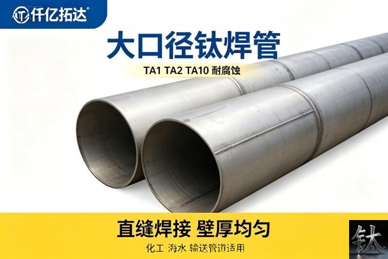
Titanium Welded Pipe 133 to 508 mm: Ovality, Seam Position and the Fit-Up Dimension Chain
| Specification | Nominal size: 133 to 508 mm outside diameter welded pipe formed from plate or coil under ASTM B862 |
|---|---|
| Applicable Standard | Mating part: weld neck flange bore, butt weld fitting bevel, adjacent pipe spool and the branch opening saddle |
| Material Condition | Governing drawing: piping isometric revision, ASTM B862 edition named in the PO and the ASME B16.5 or B16.9 edition for the mating part |
| Inspection & Packaging | Tolerance basis: formed-pipe ovality and circumference, wall thickness at the seam, seam angular position, bevel angle and root face, and high-low misalignment at fit-up |
| Reference Price | $12.00 – $20.00 |
Product Description: OD 133 and 508 mm sit in different NPS segments. Formed-pipe ovality, seam position and bevel match decide field fit-up, not the size list
Product Overview
Titanium Welded Pipe 133 to 508 mm: Ovality, Seam Position and the Fit-Up Dimension Chain
A titanium welded pipe ordered at 508 mm outside diameter does not fit its flange or its next spool the way a 133 mm pipe does, because the two diameters sit in different nominal size segments and a formed pipe carries ovality and a longitudinal seam that a size list never describes. The controlling number is not the OD on the purchase order but the fit-up gap: the mating bore or bevel dimension minus the measured OD and ovality, minus twice the wall mismatch and the seam crown allowance. Our ASTM B862 welded pipe guide, our 114 mm and 12000 mm tube page and our what B16.5 hides guide settle what welded pipe is and which standard and length to buy; this article starts where they stop, at the fit-up gap measured at the flange bore and the fitting bevel.
At a Glance: Eight Decisions Between a Size Range and a Field Fit-Up
| Item | What the decision turns on |
|---|---|
| The short answer | A size range is not a fit; 133 and 508 mm sit in different nominal segments and do not assemble with the same tools or tolerance budget |
| The governing identity | Fit-up gap equals the mating bore or bevel dimension minus the measured pipe OD and ovality, minus twice the wall mismatch and the seam crown allowance |
| The first trap | OD 133 mm is not a standard nominal pipe size while 508 mm matches a widely used nominal OD, so ordering by OD alone mixes two sizing systems |
| The form trap | B862 pipe is formed from plate or coil and welded, so ovality and seam crown are forming results rather than catalogue dimensions |
| The seam trap | The longitudinal seam must be mapped and kept clear of girth welds and branch openings before any spool is cut |
| The length trap | A 12 m fixed length sets where field welds fall, and a flange or fitting bevel has to be prepared at that exact station |
| The misalignment trap | At 508 mm a small OD or ovality error becomes a large high-low step at the root, and shims do not fix a butt weld |
| The one document | A 14-line Welded Pipe Fit-Up and Dimension Chain Verification Sheet: check, basis, method, criterion, who signs |
Rows three and five hide most of the rework, and our welded versus seamless selection guide plus our Grade 2 welded tube page give the product context. A stockholder can certify a heat number and a delivered OD; it cannot certify the fit-up gap at your flange bore without measuring the ovality and the seam crown on that length.
The NPS-Segment Trap: 133 and 508 Do Not Fit the Same Way
Outside diameter 133 mm is not a standard nominal pipe size, while 508 mm corresponds to a widely used nominal OD in the stainless and nonferrous pipe tables. Ordering a range written as 133 to 508 mm therefore mixes two sizing systems on one purchase order, and mating flanges, fittings and branch saddles are usually selected by nominal size rather than by measured OD. Our ASTM B862 welded pipe guide and our PN10 PN16 and B16.5 flange page set out the product and the flange context; confirm the actual OD and its mating nominal designation against the pipe standard edition named in the purchase order before any spool is cut. This is a known input from the specification layer, not a fit-up conclusion.
The practical consequences are geometric. At 133 mm a spool can be rotated and aligned by hand with light clamps; at 508 mm a small ovality error becomes a significant high-low step at the root, alignment needs strongbacks or internal clamps, and a bevel has to be machined rather than hand ground. Branch openings scale too: a saddle cut on a 508 mm run intercepts a much flatter local curvature, so the same template does not serve both ends of the range.
A nominal OD is an ordering label. The measured OD, ovality and seam position on this length are the fit-up dimensions.
The trap closes when a fabricator treats the range as one product family and issues one bevel preparation sheet for all diameters. Confirm the named standard edition for each nominal size, the wall schedule that goes with it, and the flange bore or fitting bevel that will receive it. Our Grade 2 welded process pipe page and our B363 elbow tee and reducer stock page show the mating parts involved.
Where the Tolerance Goes: Ovality, Wall Mismatch and the Root Gap Chain
The fit-up gap is one identity, not a tolerance. The usable root condition equals the measured bore or bevel of the mating part, minus the measured pipe OD and its ovality at that station, minus twice the wall thickness mismatch across the joint, minus the seam crown allowance. Written this way the arithmetic is deterministic, and none of its terms is a supplier figure.
Ovality acts twice. It changes the local OD that the flange bore or the fitting bevel sees, and it changes the wall alignment at the root even when the two parts share the same nominal OD. Measure the OD at a station grid around the circumference and along the length, then feed the local maxima and minima into the gap calculation rather than the nominal value. Our B862 welded pipe guide names the product standard and our B861 seamless pipe page gives the contrast in form; name the edition before quoting any band.
Wall mismatch is the third term. Two lengths can share a nominal schedule and still differ at the local minimum, so a butt joint prepared to the same bevel leaves a step on the inside. Published ovality, roundness and high-low limits disagree between pipe standards, fabrication codes and project specifications, so we publish the conflict rather than one value.
The Dimension Nobody Measures: Seam Position and the 12 m Fixed Length
A welded pipe carries a longitudinal seam, and that seam has an angular position. At fit-up it must be mapped, marked and kept clear of the girth weld intersection, the branch opening and the flange weld where the local stress and the inspection access are worst. A seam hidden under a saddle cut or crossed by a branch opening is a geometry problem before it is a welding problem.
Length is the second silent dimension. A 12 m fixed length determines where the field girth welds fall, and a flange or a fitting has to be prepared at exactly that station. If the pipe is cut to resolve a fit-up problem, the remaining length changes, the next weld moves, and a prefabricated spool no longer matches its support positions.
Seam angle and cut length are fit-up dimensions. Once a spool is cut, both the weld map and the flange station move with it.
A replacement length from another heat or another forming setup resets OD, ovality, wall and seam position at once. Re-run the OD station grid, re-mark the seam, re-check the weld map and re-issue the verification sheet before restarting. Our 25 mm tube page shows how the same traceability logic applies at small diameters and our tube receiving inspection page covers the identity gate at receipt.
Three Fit-Up Interfaces: Pipe to Flange, Pipe to Fitting, Pipe to Pipe
The flange bore and the weld neck bevel
A weld neck flange is selected by nominal size and rating, but its bore and its weld end bevel are dimensioned by the flange standard and the pipe schedule. A formed pipe whose measured OD sits at the high side of the ovality band can pass the size check and still fail to enter the bore or leave an uneven weld end land. Check the bore, the bevel angle and the root face against the named ASME B16.5 edition and the pipe schedule before tacking.
The butt weld fitting bevel and the schedule transition
Elbows, tees and reducers are usually ordered by nominal size and schedule, while a formed pipe arrives with a measured OD and a local wall minimum. Where the schedules differ, the joint needs a transition bevel, and where the OD differs the two bevels do not share a centre line. Machine the transition from measured dimensions rather than nominal ones.
The pipe to pipe girth weld and the high-low step
At the girth weld the two measured OD profiles, the two wall minima and the two seam positions meet. Internal alignment is what controls the root, so a high-low step measured on the outside can be misleading. Use an internal clamp or strongbacks where the diameter allows, measure high-low at mapped stations around the circumference and record the root gap before welding.
When the Published Ovality and Misalignment Numbers Disagree: Publish the Conflict, Not One Value
Ask several sources for an ovality limit, a roundness tolerance, a high-low acceptance value or a permitted seam crown and you get a spread, not one table. Pipe product standards, fabrication codes, project specifications and our own pages use different reference diameters, wall schedules and measuring bases. Presenting any one figure as the correct value would be false precision.
| Quantity | Figures in conflict | Why they disagree | What to confirm |
|---|---|---|---|
| Ovality or out of roundness | One pipe note quotes a percentage of nominal OD; a project specification quotes an absolute difference between maximum and minimum measured OD; a forming guide quotes no formed-pipe figure at all | Different reference diameter, measuring base and whether the value applies before or after sizing | Named standard edition, station grid and whether the measurement is at the end or mid length |
| High-low misalignment at the root | One fabrication code quotes a fraction of wall thickness; a project specification quotes an absolute maximum; a welding note defers to the qualified WPS | Different acceptance bases and internal versus external measurement | WPS revision, internal measurement and who accepts the joint |
| Wall thickness at the longitudinal seam | Mill notes quote a minus tolerance on nominal wall; a forming guide adds a local thinning allowance at the seam; a buyer page quotes no seam figure | Different forming routes, weld bead conditioning and definitions of local minimum | MTC, ultrasonic survey at the seam and the named acceptance clause |
| Seam angular clearance from branch openings | Some project specifications name a minimum angular separation; others require only that the seam not be intersected; some are silent | Different branch reinforcement rules and inspection access | Isometric revision, branch detail and the seam mark on the length |
| Flange bore versus pipe OD clearance | Flange tables give a bore by nominal size and schedule; pipe notes quote an OD tolerance band; a fit-up guide adds a weld gap allowance | Different sizing systems and whether the clearance is radial or diametral | ASME B16.5 edition, measured OD grid and the weld gap in the WPS |
| Bevel angle and root face | One WPS quotes a fixed included angle; another scales it with wall thickness; a fit-up note adds a land tolerance | Different wall schedules, welding processes and root gap targets | Qualified WPS revision, angle gauge reading and a mapped land survey |
Our B862 welded pipe guide and our what a dimensional standard hides guide show why the edition must be named, and our flange RT test report page shows the form of a traceable record. A chart is a buying aid; the measured OD grid, the seam map and the signed verification sheet are the tie breakers. Chapter ten gives six actions that settle the numbers.
Two Independent Check Lines: Field Fit-Up Here, Buying and Receipt There
Whether a welded pipe is delivered against ASTM B862 or ASME SB-862, what its size range and schedule are, and whether it passed eddy current, ultrasonic or hydrostatic testing at the mill are specification and receipt questions, not field fit-up questions. They belong to the buying and receiving line that our B862 welded pipe guide, our welded versus seamless selection guide and our tube receiving inspection page already cover. We do not restate that line here.
Keep the two records separate. The buying and receiving file holds the purchase order, the mill certificate, the named standard edition, the test reports and the fixed length record. The fit-up file holds the piping isometric revision, the OD and ovality station grid, the wall minimum survey at the seam, the seam angle map, the cut and weld map, the flange bore and bevel check, the high-low measurement and the signed 14-line sheet.
Limitations and Failure Conditions: Eight Welded Pipe Fit-Up Rejection Triggers
[Geometry] Trigger 1 - Spool laid out from the nominal OD with no ovality or wall mismatch allowance
Recalculate the fit-up gap from the chain: mating bore or bevel minus the measured OD and ovality, minus twice the wall mismatch and the seam crown allowance. A layout that equates the ordered OD with the assembled OD omits the forming result. Judge against the approved calculation and the piping isometric revision.
[Geometry] Trigger 2 - OD written as 133 mm mixed with a nominal 508 mm size on one purchase order
Name the pipe standard edition and the nominal designation that each diameter maps to, then confirm the mating flange bore and fitting bevel by that same designation. Mixing an outside diameter with a nominal size produces a flange that cannot be selected correctly. Our PN10 PN16 and B16.5 flange page gives the flange context.
[Geometry] Trigger 3 - Ovality measured at one station instead of a circumferential and longitudinal grid
Map OD at several angular positions at both ends and at mid length, then feed local maxima and minima into the gap calculation. A single diameter reading cannot describe a formed cross section. Our Grade 2 welded tube page gives the form context.
[Fit] Trigger 4 - Longitudinal seam crossed by a girth weld, a branch opening or a flange weld
Mark the seam angle at both ends, carry the mark through cutting and beveling, and confirm the clearance against the piping isometric revision and the branch detail. A seam hidden under a saddle cut is a geometry reject before it is a welding reject. Our ASTM B363 fittings page gives the fitting context.
[Fit] Trigger 5 - High-low step at the root left unmeasured because the outside looked aligned
Measure high-low internally at mapped stations around the circumference with an internal clamp or strongbacks where the diameter allows, then compare with the qualified WPS criterion. At 508 mm a small external reading can hide a large internal step. Our GTAW shielding guide covers the root discipline.
[Fit] Trigger 6 - Flange bore and weld end bevel prepared to nominal schedule rather than measured wall
Check the bore, the bevel angle and the root face against the named ASME B16.5 edition and the measured wall minimum at the joint, then machine the transition from measured dimensions. Two lengths sharing a nominal schedule can still differ at the local minimum. Our what B16.5 hides guide makes the parallel point.
[Process] Trigger 7 - Length re-cut to solve a fit-up problem without updating the field weld map
Any re-cut changes the remaining length, moves the next field weld and shifts a prefabricated spool away from its support positions. Re-issue the cut and weld map, re-check the flange station and re-issue the 14-line sheet before restarting. Our 114 mm and 12000 mm tube page gives the length context.
[Process] Trigger 8 - No OD grid, no seam map, no signed verification sheet or lost heat-to-length traceability
Reconcile every delivered length, cut spool and welded joint against the heat number, the piping isometric revision, the seam map and the signed sheet. A spool whose OD grid cannot be rebuilt is a reject regardless of a clean mill certificate or a passed hydrostatic test. Our tube receiving inspection page shows what the receipt record proves.
The 14-Line Welded Pipe Fit-Up and Dimension Chain Verification Sheet
| # | Fit-up check | Basis drawing or standard edition | Measurement method | Acceptance criterion | Who signs |
|---|---|---|---|---|---|
| 1 | Standard edition, grade, nominal size and schedule named | Purchase order and MTC | Document review | One designation with revision | Buyer QA |
| 2 | Nominal size mapped to measured OD for each diameter | Named pipe standard edition | Document review and OD survey | Single sizing system, no mixed designations | Piping engineer |
| 3 | Fixed length and field weld map issued | Piping isometric revision | Drawing review and tape survey | Weld stations and supports located | Piping engineer |
| 4 | OD and ovality surveyed on a station grid | Measurement plan and drawing revision | Calibrated OD gauge at mapped angles and stations | Maxima and minima logged at both ends | Fabrication inspector |
| 5 | Wall minimum at the longitudinal seam measured | MTC and named acceptance clause | Ultrasonic survey at and away from the seam | Local minimum logged, mismatch carried into chain | Fabrication inspector |
| 6 | Seam angular position marked at both ends | Isometric revision and seam record | Protractor on the marked length | Seam angle logged and carried through cutting | Fabrication inspector |
| 7 | Seam clearance from girth weld and branch opening | Isometric revision and branch detail | Layout check on the marked spool | No intersection, clearance inside criterion | Piping engineer |
| 8 | Mating flange bore and fitting bevel identified | ASME B16.5 or B16.9 edition in the PO | Bore gauge and bevel angle check | Bore and bevel stated per nominal size | Fabrication inspector |
| 9 | Fit-up gap calculation published and signed | General arrangement and dimension chain | Independent recalculation from the measured grid | Gap covers bore, mismatch and seam crown | Piping engineer |
| 10 | Bevel angle, root face and land at the prepared end | Qualified WPS revision and joint detail | Angle gauge and feeler gauge around the circumference | Bevel uniform, land inside criterion | Welding inspector |
| 11 | High-low measured internally at fit-up | WPS high-low acceptance clause | Internal gauge at mapped stations | Step inside criterion, root gap logged | Welding inspector |
| 12 | Back purge and root protection arrangement recorded | GTAW shielding procedure | Setup review before welding | Purge established, joint released | Welding inspector |
| 13 | Heat-to-length and length-to-joint traceability reconciled | MTC, seam map and production record | Identity review across cuts and changes | One heat and one seam map per released joint | Quality lead |
| 14 | Cumulative fit to flange, fitting and next spool with signed sheet | General arrangement and dimension chain | Measure offset at fit-up and reconcile records | Offset inside criterion, hold released | Quality lead and buyer |
Line four is often answered with one diameter reading instead of a circumferential grid, line five with a nominal schedule instead of a measured wall minimum, line seven with an unmarked seam and line eleven with an outside alignment check that hides the root step. Our B862 welded pipe guide and our tube receiving inspection page separate buying and receipt evidence from fit-up work. Our WPS qualification guide shows the form of a signed joint record, and our equipment leak repair guide shows the downstream cost of an undocumented weld.
Six Verification Actions When Ovality and Misalignment Figures Conflict
- Require every acceptance value to carry its document, revision and clause. Name the ASTM B862 edition, the ASME B16.5 or B16.9 edition for the mating part, the piping isometric revision and the qualified WPS before quoting any ovality or high-low band. Our B862 welded pipe guide is a product reference, not the governing clause.
- State the sample condition and measuring method: as formed, sized or bevelled, and the OD from a circumferential and longitudinal station grid rather than the nominal figure. Our Grade 2 welded tube page gives the buying baseline.
- Publish the fit-up chain before cutting any spool: measured OD and ovality, the mating bore or bevel, twice the wall mismatch, the seam crown allowance and the resulting root gap. A calculation is a prediction; the measured high-low survey at fit-up is the record. Our B363 fitting stock page lists the mating parts.
- Name who reviews the conflict: buyer quality, piping engineer, fabrication supervisor and welding inspector, with authority to accept or hold. Our WPS qualification guide shows that qualification is a signed decision.
- Keep records independent with their own dates: purchase order and MTC, OD and ovality grid, seam angle map, wall minimum survey, cut and weld map, flange bore and bevel check, high-low reading and the signed verification sheet. Our flange RT report page shows the form of a traceable record.
- Use trigger-based re-verification: any length change, heat change, re-cut, re-bevelling, seam re-marking or opened hold forces reassessment. Our equipment leak repair guide and our equipment layup guide show the downstream cost.
Most of these cost nothing at planning and a great deal after a spool is cut and a field weld is ground out. Ask for the purchase order clause, the OD and ovality grid, the seam map, the cut and weld map and the signed verification sheet for the same length. We are a stockholder, not the author of your piping isometric; where figures come from published guides we label them, and where they disagree we give the disagreement and the action.
Summary: Choose a Nominal-Size Layout if, Choose a Re-Measured Fit-Up Chain if
Choose X if: a nominal-size layout with a signed verification sheet
- The purchase order names the standard edition, the nominal size and schedule, the fixed length and the piping isometric revision, and the flange bore and fitting bevel are stated.
- A circumferential and longitudinal station grid gives the measured OD and ovality at both ends, and the fit-up chain uses twice the wall mismatch and the seam crown allowance.
- The seam angle is mapped and kept clear of the girth weld, the branch opening and the flange weld on the approved weld map.
- The flange bore, the fitting bevel, the root gap, the high-low step and the 14-line sheet are signed per line before release.
Escalate to a fit-up hold or an isometric review if:
- A clean mill certificate or a clean hydrostatic test report is the only fit-up evidence offered; our hydrostatic test guide is a later gate, not this one.
- The order mixes an OD written as 133 mm with a nominal size written as 508 mm and no piping standard edition is named.
- Published ovality, high-low or seam clearance figures disagree and no one has named the governing WPS.
- The seam was cut through by a branch opening or was not marked before the spool was bevelled.
- The OD grid, the seam map, the cut and weld map or a signed verification sheet is missing.
Choose Y if: a re-measured fit-up chain and a new weld map
- The length was substituted by another heat or another forming setup; settle the dimension chain again before cutting. Our tube receiving inspection page covers the identity gate at receipt.
- The design controls a flange bore or a branch reinforcement, so a wall mismatch cannot be absorbed. Our process equipment buyers guide gives the equipment context.
- The buyer cannot produce an OD grid, a seam map or a signed verification sheet; set up the fabrication records first.
- Welded versus seamless selection is still in dispute; keep that on the buying line and read our welded versus seamless guide while the fit-up line stays independent.
The whole subject reduces to one sentence: a nominal OD is not a fit, because the size list tells you what to order while the tolerance chain tells you whether the formed pipe will line up with the flange, the fitting and the next spool. When you enquire, send the nominal size and schedule, the standard edition, the fixed length, the piping isometric revision, the measured OD grid and the seam position. We are a Baoji China Titanium Valley titanium stockholder with roughly 800 tonnes in stock, about 80 tonnes of it in tube and pipe; we cut to non-standard and small-batch sizes, work from customer drawings, read and certify to ASTM, ASME and GB standards, export-pack in house, and dispatch confirmed in-stock orders the same day. Send us the piping isometric and the OD survey, and we will tell you what we can ship and which decisions belong with your team. Request a quote
Frequently Asked Questions
Does the OD range from 133 to 508 mm mean one fit-up procedure covers the whole order?
A range does not define a fit-up procedure. OD 133 mm is not a standard nominal pipe size while 508 mm corresponds to a widely used nominal OD, so one purchase order can mix two sizing systems. Ovality, alignment tooling, branch saddle curvature and bevel preparation all change across that span.
Will a clean B862 mill certificate and a passed hydrostatic test prove the spool fits?
A certificate and a hydrostatic test do not prove field fit-up. They prove the heat, the grade, the delivered OD band and the pressure integrity of the pipe as manufactured; they do not prove the ovality on your length, the wall minimum at the seam, the seam angular position or the fit-up gap to your flange bore. Those are measured at the fabrication gate.
Why must the longitudinal weld seam be marked before the spool is cut?
Because the seam has an angular position that must stay clear of the girth weld intersection, the branch opening and the flange weld where stress and inspection access are most demanding. Cutting and beveling remove the visible seam, so an unmarked length loses the information needed to rotate it correctly. Mark the seam angle at both ends, carry the mark through cutting and confirm the clearance against the piping isometric revision and the branch detail.
How much ovality and high-low misalignment are acceptable at a 508 mm butt weld?
There is no single published value that governs. One pipe note quotes ovality as a percentage of nominal OD, a project specification quotes an absolute maximum to minimum difference, and a fabrication code quotes high-low as a fraction of wall thickness while a welding note defers to the qualified WPS. The figures disagree because reference diameters and measuring bases differ. We publish the conflict rather than one figure.
Can a length be re-cut to fix a fit-up problem without changing anything else?
A re-cut changes more than the length. It moves the next field weld, shifts a prefabricated spool away from its support positions, changes the flange station and consumes the cut allowance. Re-issue the cut and weld map, re-check the flange bore and bevel at the new station, re-survey the OD grid and re-issue the 14-line verification sheet before restarting.
Who signs the OD station grid and the high-low measurement?
The fabrication inspector signs the OD and ovality station grid against the measurement plan and the piping isometric revision, and the welding inspector signs the internal high-low measurement against the qualified WPS acceptance clause. A single diameter reading is not a grid, and an outside alignment check does not describe the root. Published ovality figures disagree, so name the governing edition, measure at mapped angular positions and confirm the local minima before the joint is released.
Is the fit-up check the same as the welded versus seamless buying decision?
The buying decision and the fit-up check are two independent lines at two gates. The buying line decides whether welded or seamless pipe is right for the service, using the purchase order, the named standard edition, the schedule, the test reports and the fixed length record. The fit-up line decides whether that length lines up with the flange bore, the fitting bevel and the next spool, using the isometric revision, the OD grid, the wall survey, the seam map, the cut and weld map and the signed verification sheet.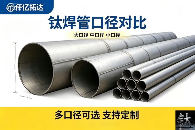
Titanium Welded Pipe 133 to 508 mm: Ovality, Seam Position and the Fit-Up Dimension Chain
A titanium welded pipe ordered at 508 mm outside diameter does not fit its flange or its next spool the way a 133 mm pipe does, because the two diameters sit in different nominal size segments and a formed pipe carries ovality and a longitudinal seam that a size list never describes. The controlling number is not the OD on the purchase order but the fit-up gap: the mating bore or bevel dimension minus the measured OD and ovality, minus twice the wall mismatch and the seam crown allowance. Our ASTM B862 welded pipe guide, our 114 mm and 12000 mm tube page and our what B16.5 hides guide settle what welded pipe is and which standard and length to buy; this article starts where they stop, at the fit-up gap measured at the flange bore and the fitting bevel.
At a Glance: Eight Decisions Between a Size Range and a Field Fit-Up
| Item | What the decision turns on |
|---|---|
| The short answer | A size range is not a fit; 133 and 508 mm sit in different nominal segments and do not assemble with the same tools or tolerance budget |
| The governing identity | Fit-up gap equals the mating bore or bevel dimension minus the measured pipe OD and ovality, minus twice the wall mismatch and the seam crown allowance |
| The first trap | OD 133 mm is not a standard nominal pipe size while 508 mm matches a widely used nominal OD, so ordering by OD alone mixes two sizing systems |
| The form trap | B862 pipe is formed from plate or coil and welded, so ovality and seam crown are forming results rather than catalogue dimensions |
| The seam trap | The longitudinal seam must be mapped and kept clear of girth welds and branch openings before any spool is cut |
| The length trap | A 12 m fixed length sets where field welds fall, and a flange or fitting bevel has to be prepared at that exact station |
| The misalignment trap | At 508 mm a small OD or ovality error becomes a large high-low step at the root, and shims do not fix a butt weld |
| The one document | A 14-line Welded Pipe Fit-Up and Dimension Chain Verification Sheet: check, basis, method, criterion, who signs |
Rows three and five hide most of the rework, and our welded versus seamless selection guide plus our Grade 2 welded tube page give the product context. A stockholder can certify a heat number and a delivered OD; it cannot certify the fit-up gap at your flange bore without measuring the ovality and the seam crown on that length.
The NPS-Segment Trap: 133 and 508 Do Not Fit the Same Way
Outside diameter 133 mm is not a standard nominal pipe size, while 508 mm corresponds to a widely used nominal OD in the stainless and nonferrous pipe tables. Ordering a range written as 133 to 508 mm therefore mixes two sizing systems on one purchase order, and mating flanges, fittings and branch saddles are usually selected by nominal size rather than by measured OD. Our ASTM B862 welded pipe guide and our PN10 PN16 and B16.5 flange page set out the product and the flange context; confirm the actual OD and its mating nominal designation against the pipe standard edition named in the purchase order before any spool is cut. This is a known input from the specification layer, not a fit-up conclusion.
The practical consequences are geometric. At 133 mm a spool can be rotated and aligned by hand with light clamps; at 508 mm a small ovality error becomes a significant high-low step at the root, alignment needs strongbacks or internal clamps, and a bevel has to be machined rather than hand ground. Branch openings scale too: a saddle cut on a 508 mm run intercepts a much flatter local curvature, so the same template does not serve both ends of the range.
A nominal OD is an ordering label. The measured OD, ovality and seam position on this length are the fit-up dimensions.
The trap closes when a fabricator treats the range as one product family and issues one bevel preparation sheet for all diameters. Confirm the named standard edition for each nominal size, the wall schedule that goes with it, and the flange bore or fitting bevel that will receive it. Our Grade 2 welded process pipe page and our B363 elbow tee and reducer stock page show the mating parts involved.
Where the Tolerance Goes: Ovality, Wall Mismatch and the Root Gap Chain
The fit-up gap is one identity, not a tolerance. The usable root condition equals the measured bore or bevel of the mating part, minus the measured pipe OD and its ovality at that station, minus twice the wall thickness mismatch across the joint, minus the seam crown allowance. Written this way the arithmetic is deterministic, and none of its terms is a supplier figure.
Ovality acts twice. It changes the local OD that the flange bore or the fitting bevel sees, and it changes the wall alignment at the root even when the two parts share the same nominal OD. Measure the OD at a station grid around the circumference and along the length, then feed the local maxima and minima into the gap calculation rather than the nominal value. Our B862 welded pipe guide names the product standard and our B861 seamless pipe page gives the contrast in form; name the edition before quoting any band.
Wall mismatch is the third term. Two lengths can share a nominal schedule and still differ at the local minimum, so a butt joint prepared to the same bevel leaves a step on the inside. Published ovality, roundness and high-low limits disagree between pipe standards, fabrication codes and project specifications, so we publish the conflict rather than one value.
The Dimension Nobody Measures: Seam Position and the 12 m Fixed Length
A welded pipe carries a longitudinal seam, and that seam has an angular position. At fit-up it must be mapped, marked and kept clear of the girth weld intersection, the branch opening and the flange weld where the local stress and the inspection access are worst. A seam hidden under a saddle cut or crossed by a branch opening is a geometry problem before it is a welding problem.
Length is the second silent dimension. A 12 m fixed length determines where the field girth welds fall, and a flange or a fitting has to be prepared at exactly that station. If the pipe is cut to resolve a fit-up problem, the remaining length changes, the next weld moves, and a prefabricated spool no longer matches its support positions.
Seam angle and cut length are fit-up dimensions. Once a spool is cut, both the weld map and the flange station move with it.
A replacement length from another heat or another forming setup resets OD, ovality, wall and seam position at once. Re-run the OD station grid, re-mark the seam, re-check the weld map and re-issue the verification sheet before restarting. Our 25 mm tube page shows how the same traceability logic applies at small diameters and our tube receiving inspection page covers the identity gate at receipt.
Three Fit-Up Interfaces: Pipe to Flange, Pipe to Fitting, Pipe to Pipe
The flange bore and the weld neck bevel
A weld neck flange is selected by nominal size and rating, but its bore and its weld end bevel are dimensioned by the flange standard and the pipe schedule. A formed pipe whose measured OD sits at the high side of the ovality band can pass the size check and still fail to enter the bore or leave an uneven weld end land. Check the bore, the bevel angle and the root face against the named ASME B16.5 edition and the pipe schedule before tacking.
The butt weld fitting bevel and the schedule transition
Elbows, tees and reducers are usually ordered by nominal size and schedule, while a formed pipe arrives with a measured OD and a local wall minimum. Where the schedules differ, the joint needs a transition bevel, and where the OD differs the two bevels do not share a centre line. Machine the transition from measured dimensions rather than nominal ones.
The pipe to pipe girth weld and the high-low step
At the girth weld the two measured OD profiles, the two wall minima and the two seam positions meet. Internal alignment is what controls the root, so a high-low step measured on the outside can be misleading. Use an internal clamp or strongbacks where the diameter allows, measure high-low at mapped stations around the circumference and record the root gap before welding.
When the Published Ovality and Misalignment Numbers Disagree: Publish the Conflict, Not One Value
Ask several sources for an ovality limit, a roundness tolerance, a high-low acceptance value or a permitted seam crown and you get a spread, not one table. Pipe product standards, fabrication codes, project specifications and our own pages use different reference diameters, wall schedules and measuring bases. Presenting any one figure as the correct value would be false precision.
| Quantity | Figures in conflict | Why they disagree | What to confirm |
|---|---|---|---|
| Ovality or out of roundness | One pipe note quotes a percentage of nominal OD; a project specification quotes an absolute difference between maximum and minimum measured OD; a forming guide quotes no formed-pipe figure at all | Different reference diameter, measuring base and whether the value applies before or after sizing | Named standard edition, station grid and whether the measurement is at the end or mid length |
| High-low misalignment at the root | One fabrication code quotes a fraction of wall thickness; a project specification quotes an absolute maximum; a welding note defers to the qualified WPS | Different acceptance bases and internal versus external measurement | WPS revision, internal measurement and who accepts the joint |
| Wall thickness at the longitudinal seam | Mill notes quote a minus tolerance on nominal wall; a forming guide adds a local thinning allowance at the seam; a buyer page quotes no seam figure | Different forming routes, weld bead conditioning and definitions of local minimum | MTC, ultrasonic survey at the seam and the named acceptance clause |
| Seam angular clearance from branch openings | Some project specifications name a minimum angular separation; others require only that the seam not be intersected; some are silent | Different branch reinforcement rules and inspection access | Isometric revision, branch detail and the seam mark on the length |
| Flange bore versus pipe OD clearance | Flange tables give a bore by nominal size and schedule; pipe notes quote an OD tolerance band; a fit-up guide adds a weld gap allowance | Different sizing systems and whether the clearance is radial or diametral | ASME B16.5 edition, measured OD grid and the weld gap in the WPS |
| Bevel angle and root face | One WPS quotes a fixed included angle; another scales it with wall thickness; a fit-up note adds a land tolerance | Different wall schedules, welding processes and root gap targets | Qualified WPS revision, angle gauge reading and a mapped land survey |
Our B862 welded pipe guide and our
Request a Quote for Titanium, Nickel or Zirconium
Tell us what you need. Send the points below and we reply with live stock status, price and lead time — usually the same day.
Send us these 6 points (or just attach your drawing / old supplier spec)
| 1 | Material grade — Gr2 / Gr5 / Gr7 / Gr12, Ni200 / Ni201 / Monel 400, Zr702… |
| 2 | Form — plate / tube / bar / wire / fitting / flange / fastener / equipment |
| 3 | Size & tolerance — thickness×width×length / OD×WT / diameter |
| 4 | Quantity — kg / pcs / m (small batch and non-standard sizes welcome) |
| 5 | Standard — ASTM B265 / B338 / B348, ASME B16.5, EN 1092-1… |
| 6 | Application & destination — helps us pick the right grade and certifications |
Not sure how to fill this? Send your drawing or an old supplier's specification sheet — we will break it down for you.
Reach us directly
Email: [email protected]
WhatsApp / WeChat:+8618829679311 leave your number on the form
Or use the inquiry form on this page — attach your drawing and we will respond within one business day.
Why buyers come to us
Stock holder in Baoji Titanium Valley with ~800 t inventory · cut-to-size and small batch · drawing-based machining for non-standard parts · we read ASTM / ASME / GB specs · export experience · same-day response on quotes.
Tell us your requirement — grade, size and quantity. We reply within 24 hours.
Prefer chat? WhatsApp +86 188 2967 9311 or email [email protected].

- Titanium Price Today (9 Nov 2026): Plate, Tube, Rod & Wire
- What is Titanium Flange | ASME B16.5 ASTM B381 Gr2 Gr5 Titanium Flan
- ASME B16.5 Titanium Flange Grade2 DN100-DN600 Class150/300 FOB
- Gr2 Titanium Sheet Price FOB Shanghai | ASTM B265 In Stock
- Titanium Price Today (Oct 26, 2026): China Market Report
Contact Person: Wang Xiaoning
Tel: +86-917-355-7966
Email: [email protected]
WhatsApp: +86 188 2967 9311
Company: Shaanxi Qianyi Tuoda Technology Co., Ltd
Address: Floor 4, Building 4, No. 188 Gaoxin Avenue, High-tech Zone, Baoji City, Shaanxi Province, China