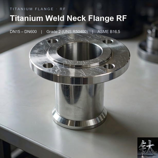
Titanium Flange Sealing Face Pair Fit-Up: The Dimension Chain When Two Passing Flanges Still Leak
| Specification | Nominal size: NPS and pressure class of both flanges, raised face 1/16 in or 1/4 in by class |
|---|---|
| Applicable Standard | Mating part: the opposing flange facing designation, gasket seating diameter and bolt pattern |
| Material Condition | Governing drawing: equipment or piping isometric revision and the ASME B16.5 edition named in the PO |
| Inspection & Packaging | Tolerance basis: RF boss height, sealing-face Ra band, PCD and bolt-hole concentricity, parallelism and gasket compression stack |
Product Description: Two flanges can each pass inspection and still leak: RF boss height, Ra, PCD concentricity and gasket compression stack into one pair fit-up chain.
Product Overview
Titanium Flange Sealing Face Pair Fit-Up: The Dimension Chain When Two Passing Flanges Still Leak
A raised face of 1/16 in (1.6 mm) on one titanium flange and one of 1/4 in (6.4 mm) on its intended mate are each compliant parts, yet the pair will not seal: the two gasket seating planes do not coincide. Two flanges that pass inspection one by one can still leak when bolted together, because a nominal match is not a fit. Our sealing-surface form page tells you which facing to select, our three-piece set page covers the bolt and gasket set, and our receiving and marking page shows what to check on arrival. That is one independent check line. This article is the second line: the pair fit-up dimension chain once the facing type is fixed. We treat the form as a known input; neither line cancels the other. Confirm every figure against the ASME B16.5 edition named in the purchase order.
At a Glance: Eight Decisions That Decide Whether a Flange Pair Seals
| Item | What the decision turns on |
|---|---|
| The short answer | Two passing flanges can still leak as a pair |
| The governing identity | The pair gasket gap sums two boss heights, two flatness values, parallelism and gasket compression |
| The raised-face trap | A 1/16 in boss and a 1/4 in boss do not share a seating plane |
| Where tolerance goes | PCD, hole spacing and concentricity errors accumulate across two flanges |
| The finish question | The Ra band and judgement method differ by B16.5 edition |
| The unlike-facing rule | Facing, class and gasket seating diameter must be read from both drawings |
| The conflict | Published heights and Ra bands disagree; publish the conflict, not one value |
| The one document | A 14-line Flange Pair Fit-Up and Dimension Chain Verification Sheet: check, basis, method, criterion, who signs |
Rows two and three hide most rework: geometry is checked per flange, the failure appears only at the pair. Our selection and seal failure page gives service context and our small-size stock flange page lists the product. A stockholder can certify a heat number; it cannot certify that two specific faces will seat.
When Two Passing Parts Still Leak: A Nominal Match Is Not a Fit
A flange inspection is written for one part. It checks a raised-face height, a finish, a bolt circle and a thickness against a table, and each part can sit inside its own band. A joint is written for two parts: whether the two seating planes meet, whether the bolt holes line up, and whether the compressed gasket sees even load around the circle. Two individually passing parts can fail all three at once, and no single-part certificate detects it.
We therefore keep two independent check lines separate, and neither cancels the other. The first belongs to our form comparison page, our three-piece set page and our receiving and marking page: which facing to select, which set to buy, what to verify on arrival. The second belongs here: the dimension chain between two fixed faces at bolt-up. We do not redo the form comparison, restate the selection or repeat the arrival list. Our page on what a dimensional standard hides makes the same point for one part; this article carries it across the joint.
A single-part tolerance guarantees the part. Only a pair dimension chain guarantees the joint. Name facing, class and edition on both drawings before comparing any number.
Where the Tolerance Goes: RF Boss Height and Sealing-Face Finish Across B16.5 Editions
Secondary references describe the raised-face height under ASME B16.5 as 1/16 in (1.6 mm) for Class 150 and 300 and 1/4 in (6.4 mm) for Class 400 and above. Those are widely reproduced figures, not a controlling value we issue. Pair two flanges on opposite sides of that split and the seating planes are offset by the difference in boss heights. Our ANSI B16.5 stock page and our PN and class page give the class context; the PO decides the edition for each piece.
A second ambiguity rides on the same number: whether tabulated thickness already includes the raised face. Some references describe the 1/16 in boss as additional to the listed minimum thickness while the 1/4 in boss is inside it; others say the designer must verify which convention the named edition uses. Measure one flange with its boss included and the other with it excluded and a face-to-face dimension is wrong by one full boss height. Our dimensional standard page covers naming the edition.
The finish adds the same risk. Current B16.5 text is quoted as a serrated finish of 125 to 250 microinch (3.2 to 6.3 micrometre) Ra for raised and flat faces, with tighter seats for tongue and groove and ring-joint flanks. Other guides carry a wider 125 to 500 microinch band. We label all as secondary references. Two faces accepted against different editions are not comparable. Our flange category page gives the range; the drawing and named edition decide the finish.
The Dimension Nobody Measures: Cumulative PCD and Bolt-Hole Concentricity
A bolt passes through two flanges, so the hole error that matters is the sum of both patterns, not either alone. ASME B16.5 drilling tolerances are commonly reproduced as plus or minus 1.5 mm (0.06 in) on bolt circle diameter, plus or minus 0.8 mm (0.03 in) on adjacent hole spacing, and bolt-circle-to-facing concentricity of 0.8 mm (0.03 in) for NPS 2-1/2 and smaller and 1.5 mm (0.06 in) for NPS 3 and larger. These are secondary values; name the edition first.
Each flange can sit inside every band and the pair can still bind. A bolt circle offset to its own face on one flange, and offset the other way on the mate, turns each shared hole into a slot with less clearance than either hole. Add spacing error around the circle and a stud that drops through one flange can jam on the second. The cumulative offset is a pair property; it appears on no single-part sheet. Our weld neck and slip-on page and our dimensional standard page give the context.
Parallelism, Face Flatness and Gasket Compression at the Joint
What the geometric stack contains
The gap the gasket must fill at any station is the sum of two raised-face heights, the local flatness of each face, the relative parallelism of the two flanges and the elastic recovery the gasket needs after compression. This is a stack, not a tolerance; the terms add around the bolt circle. A joint can be within its nominal gap at one station and open beyond the seating range at the opposite one. Our process equipment buyers guide and our pressure vessel flange page give the vessel and product context.
Why parallelism is a pair measurement
Flatness belongs to one face; parallelism belongs to the two together. Two faces can each be flat inside their own clause and still be wedged once pipe strain and bolt preload apply. Judge the assembled gap with feeler gauges or dial indicators at mapped stations, not at one reference station. We give no compression percentage here; the gasket datasheet and the drawing clause set that and must be named. Our hydrostatic test guide is a later gate, not a substitute.
Where the stack closes
Close the stack with measured inputs from both flanges, then confirm the compressed gasket sits inside its seating window at every station. A negative local gap crushes the gasket; a positive one leaves a leak path. Neither is fixed by over-torquing one bolt. Our equipment leak repair guide shows the downstream cost. Confirm every criterion against the drawing revision and named edition.
Drawing Criteria for Unlike Facings and for Re-Assembly
The first pair check is documentary. Read the facing designation, pressure class, raised-face height, gasket seating diameter and bolt pattern from both drawings; the same NPS does not grant a match. Two unlike facings cannot be bolted directly together. A raised face cannot seat against a ring-joint groove, a flat face needs a full-face gasket and must not be paired with a raised face that bends a brittle mate, and male and female or tongue and groove pairs must be matched as a complementary set. Our form comparison page already explains each form; here the form is a known input. Our blind and weld neck page gives the forms that make mixed pairs common.
Class mismatch is the same failure in disguise. A Class 150 raised face of 1/16 in and a Class 600 raised face of 1/4 in can share a nominal size yet present different seating planes, bolt circles and hole counts. Judge the pair against the general arrangement, not one part number. Our PN and class page and our titanium flange range give the class context; the drawing decides whether an adapter or a different mate is needed.
Re-assembly adds geometry a new-part inspection does not see. An old gasket impression, a radial scratch, pitting, warpage or ovality all change the seating plane. Field re-facing restores flatness and finish but removes metal from the raised face, so the boss height drops and the pair stack shifts. Re-measure boss height, finish and flatness on both flanges after any rework. Our leak repair guide and our equipment layup guide cover the service context; the pair sheet is where the re-check is signed.
When Published RF Height and Ra Figures Disagree: Publish the Conflict, Not One Value
Ask several sources for a boss height, a roughness band or the correct way to judge a finish and you get a spread, not one table. Editions, gasket datasheets, supplier guides and field practice use different definitions and vintages. Presenting one figure as correct would be false precision. The table collects secondary references, not controlling values; the controlling value is named in the purchase order, the drawing revision and the standard edition governing this pair.
| Quantity | Figures in conflict | Why they disagree | What to confirm |
|---|---|---|---|
| Raised-face height by class | 1/16 in (1.6 mm) for Class 150 and 300 and 1/4 in (6.4 mm) for Class 400 and above in most guides; a separate height tolerance is also quoted | Different editions, class splits and whether a height tolerance is stated | Named edition, both classes, measured boss height on each flange |
| Thickness includes the boss | One source says the 1/16 in boss is additional to tabulated thickness while the 1/4 in boss is inside it; another says verify the convention | Different edition conventions and definitions of flange thickness | Clause defining thickness for each flange and how face-to-face is built |
| Sealing-face roughness band | Current B16.5 text quoted at 125 to 250 microinch (3.2 to 6.3 micrometre) Ra; many piping sites and gasket notes quote 125 to 500 microinch | Legacy shop descriptions, a European allowance and gasket-maker notes mixed with the code band | Named edition clause, gasket datasheet and the agreed finish |
| Serration density and tool radius | Current text quoted at 45 to 55 grooves per inch with a tool nose radius of about 0.06 in or larger; other notes quote 30 to 55 | Different vintages and a conflation with non-code shop practice | Named clause, agreed finish and concentric or spiral serration |
| How Ra is judged | The code language is quoted as visual comparison with ASME B46.1 reference standards and not stylus instruments; field practice uses a profilometer and reads Ra as RMS | Code acceptance method versus shop habit, with Ra and RMS treated as interchangeable | Named acceptance method, comparator or instrument used and who records the reading |
| Finish for other facings | Tongue and groove and small male and female seats quoted at no more than 125 microinch; ring-joint flanks at no more than 63 microinch (1.6 micrometre) | Different face types have different seats and the figures come from different editions | Facing designation on both drawings and the named clause for that seat |
Our dimensional standard page and our mill certificate guide show why the edition must be named and what a mill record proves. A chart is a buying aid; two measured boss heights, the agreed finish method and the signed sheet are the tie breakers. Chapter ten gives six actions that settle the numbers. Confirm every criterion against the drawing revision and the named edition.
Limitations and Failure Conditions: Eight Flange Pair Fit-Up Rejection Triggers
[Geometry] Trigger 1 - The two raised-face heights come from different classes or editions that treat the boss differently
Read the class and named B16.5 edition on both drawings, then measure the boss height on each flange. A 1/16 in boss paired with a 1/4 in boss leaves the seating planes offset. Judge against the general arrangement and dimension chain. Our ANSI B16.5 stock page gives the class context. In a dispute, rebuild the pair stack from two measured heights.
[Geometry] Trigger 2 - Sealing-face Ra accepted against different editions or judged by a method the drawing does not name
Name the finish band and judgement method for both faces, then confirm the serration pattern and check for radial scratches. One face read with a comparator and the other with a stylus instrument are not comparable evidence. Our dimensional standard page covers the edition point. In a dispute, re-judge both faces with one agreed method.
[Geometry] Trigger 3 - PCD, spacing and concentricity errors accumulate so a stud will not pass both flanges
Survey the bolt pattern of both flanges against one common datum and trial-fit the studs through the assembled pair. A per-flange pass does not prove a per-joint pass. Judge the cumulative offset, not each hole alone. Our flange form page gives the product context. In a dispute, re-map the two patterns together.
[Fit] Trigger 4 - Parallelism, flatness and gasket compression stack outside the seating window at one station
Measure the assembled gap with feeler gauges or dial indicators at mapped stations, then compute the local stack. A joint inside its nominal gap at one station and open at the opposite one cannot be fixed by over-torquing one bolt. Our process equipment buyers guide gives the vessel context. In a dispute, re-align and re-map the gap.
[Fit] Trigger 5 - Two unlike facings or incompatible classes bolted together on the strength of a shared NPS
Compare facing designation, class, gasket seating diameter and bolt pattern on both drawings before bolt-up. A raised face cannot seat against a ring-joint groove and a flat face cannot be paired with a raised face that bends a brittle mate. Our form comparison page explains the forms; the pair drawing decides compatibility. In a dispute, hold the joint and specify the correct mate.
[Fit] Trigger 6 - Re-assembly reuses an old gasket impression or a re-faced boss height without re-checking the pair chain
Inspect the used face for the old impression, radial scratches, pitting, warpage and ovality, then re-measure the boss height and finish after any field re-facing. Metal removed from the raised face shifts the pair stack. Our leak repair guide covers the service context. In a dispute, re-survey both faces before release.
[Process] Trigger 7 - One flange is substituted by another edition, class or facing without recomputing the pair chain
Any change of edition, class, facing or heat resets the boss height, finish and bolt pattern that feed the stack. Re-read both drawings, re-measure both flanges, re-trial-fit the studs and re-issue the signed sheet. A substitute flange that passed its own inspection is still a reject until the pair is rechecked. Our cut-to-drawing page covers the non-standard sizes that make this common.
[Process] Trigger 8 - No measurement map, no signed pair sheet or lost link between the two flanges and their drawing revisions
Reconcile each flange against its heat number, its drawing revision and the signed 14-line sheet, with both patterns and both faces logged against one datum. A pair whose stack cannot be rebuilt is a reject regardless of two clean certificates. Our flange test report page and our WPS qualification guide show what a signed record looks like. In a dispute, restore two-part traceability.
The 14-Line Flange Pair Fit-Up and Dimension Chain Verification Sheet
| # | Fit-up check | Basis drawing or edition | Measurement method | Acceptance criterion | Who signs |
|---|---|---|---|---|---|
| 1 | Facing, class and edition named on both flanges | Both POs and drawings | Document review | One designation per flange | Buyer QA |
| 2 | Raised-face height by class confirmed for each | Named edition and class | Check the named table | Both heights stated and equal | Fabricator engineer |
| 3 | Thickness includes the boss stated for both | Edition clause | Drawing review | One convention applied to both | Design engineer |
| 4 | Boss height measured on each flange | Drawing revision | Depth micrometer at mapped points | Difference inside criterion | Fabrication inspector |
| 5 | Finish band and judgement method named | Named clause and gasket datasheet | Document review | One band and one method | Quality lead |
| 6 | Ra, serration and radial scratches checked on both | Agreed finish method | B46.1 comparator or named instrument | No direct leak path, finish inside band | Fabrication inspector |
| 7 | Bolt circle diameter measured on both | Named drilling tolerance | CMM against one datum | Deviation into the stack | Fabrication inspector |
| 8 | Adjacent hole spacing measured on both | Named drilling tolerance | CMM or coordinate layout | Cumulative error stated | Fabricator engineer |
| 9 | Concentricity computed as a pair offset | Named concentricity clause | Common-datum survey | Cumulative offset inside criterion | Fabricator engineer |
| 10 | Stud free-fit trial through the pair | General arrangement | Trial-fit every stud | All studs pass without force | Assembly supervisor |
| 11 | Face flatness and pair parallelism measured | Drawing flatness clause | Feeler gauge or dial indicator | Gap inside criterion at all stations | Assembly supervisor |
| 12 | Gasket compression stack computed | Gasket datasheet | Recalculation around the circle | Local gap inside seating range | Fabricator engineer |
| 13 | Unlike-facing and re-assembly face re-check | Both drawings and service record | Review and re-measurement | Designations compatible, face inside limits | Design engineer |
| 14 | Cumulative pair fit and signed sheet | General arrangement and pair chain | Measure offset, reconcile both heats | Offset inside criterion, hold released | Quality lead and buyer |
Line two is often answered with one published height instead of two measured ones, line five with one method instead of an agreed one, line nine with a per-flange reading instead of a cumulative offset. Our certificate guide and our receiving and marking page separate single-part evidence from pair work. Our export documentation FAQ covers the paperwork and our equipment leak repair guide shows the cost of an undocumented joint. A sheet without a signature column is a note. Confirm every criterion against the drawing revision and named edition.
Six Verification Actions When Ra and Raised-Face Height Figures Conflict
- Name the standard edition, drawing revision, class and facing for each flange before quoting any height or Ra band. Our dimensional standard page is a reference, not the governing clause.
- State the gauge and one common datum: a depth micrometer for the boss, a B46.1 comparator for the finish, one datum for both bolt patterns. Our flange test report page shows a recorded measurement.
- Publish a measurement map before bolt-up with both boss heights, both bolt patterns and the gap at stations around the circle. A calculation is a prediction; the mapped pair survey is the record. Our cut-to-drawing page gives the non-standard context.
- Name who reviews the conflict with authority to accept or hold: buyer quality, fabricator engineer and assembly supervisor. Our WPS qualification guide shows qualification is a signed decision.
- Keep records independent with their own dates: both POs, both boss-height surveys, the finish agreement, both bolt-pattern maps and the signed sheet. Our certificate guide covers the mill record.
- Re-verify on any edition change, substitution, field re-facing, re-assembly or opened hold. Our leak repair guide and our equipment layup guide show the downstream cost.
Most of these cost nothing at planning and a great deal after two flanges are bolted. Ask for the two drawing revisions, the two measured boss heights, the agreed finish method, the pair map and the signed sheet. We are a stockholder, not the author of your drawing; where published figures disagree we give the disagreement and the action. Our export flange page covers logistics and our hydrostatic test guide is a later gate, not a substitute. Confirm every criterion against the drawing revision and named edition.
Summary: Choose a Nominal Pair if, Choose a Re-Measured Pair if
Choose X if: a nominal pair with a signed verification sheet
- Both POs name the edition, class, facing and drawing revision, and both flanges share one class split.
- The two raised-face heights are measured and equal, with one thickness convention applied to both.
- One finish band and one judgement method are agreed, and both bolt patterns share a common datum.
- Parallelism, flatness, the gasket stack and the 14-line sheet are signed before bolt-up.
Escalate to a fit-up hold or a drawing review if:
- Two clean single-part certificates or a clean receiving check are the only pair evidence.
- The two boss heights come from different classes, or the thickness convention differs.
- Published Ra bands, boss heights or judgement methods disagree and no edition is named.
- Two unlike facings are proposed on a shared NPS, or a re-assembled face was not re-measured.
Choose Y if: a re-measured pair and a re-cut or a different mate
- One flange was substituted by another edition, class, facing or heat; settle the pair chain again. Our cut-to-drawing page covers the non-standard sizes that make this common.
- The design controls a face-to-face dimension, so a boss height difference cannot be absorbed. Our process equipment buyers guide gives the vessel context.
- The buyer cannot produce two boss-height surveys, a pair map or a signed sheet; set up the shop records first.
- Selection, set or arrival questions are in dispute; keep those on the first line and read our form comparison page while the pair line stays independent.
The whole subject reduces to one sentence: a nominal size is not a fit, because the drawing tells you what to order while the pair dimension chain tells you whether two passing flanges will actually seal. When you enquire, send both facing designations, both classes, the named standard edition, both drawing revisions, the measured raised-face heights, the bolt-pattern survey and the assembled gap map. We are a Baoji China Titanium Valley titanium stockholder with roughly 800 tonnes in stock, about 400 tonnes in plate, 80 tonnes in tube, 200 tonnes in bar and ingot and 50 tonnes in wire. We zero-cut to non-standard and small-batch sizes, machine from customer drawings, read and certify to ASTM, ASME and GB standards, export-pack in house, and dispatch confirmed in-stock orders the same day. Send us the two drawings and the pair measurement map, and we will tell you what we can ship and which decisions belong with your team. Request a quote →
Frequently Asked Questions
Can two flanges that each pass a dimensional inspection still fail to seal as a pair?
Yes. A single-part inspection checks one raised face, one bolt circle and one finish band against a table. A joint checks whether the two seating planes coincide, whether the bolt holes line up across two patterns, and whether the compressed gasket sees even load. Each flange can sit inside its own band while the cumulative pair offset falls outside the seating window. Judge the pair against the general arrangement and its dimension chain, not against two separate certificates.
Does the raised-face height have to match on both flanges of a joint?
It has to be compatible, and the class split decides it. Secondary references quote 1/16 in (1.6 mm) for Class 150 and 300 and 1/4 in (6.4 mm) for Class 400 and above, and the named edition may treat the boss as included in or additional to the tabulated thickness. Pair two flanges on opposite sides of that split and the seating planes are offset. Read the class and edition on both drawings, measure each boss height and confirm one convention. We label those figures as references, not controlling values.
How do PCD and bolt-hole concentricity tolerances accumulate across a flange pair?
A stud passes through two flanges, so usable clearance is set by the sum of both patterns against one common datum. A bolt circle offset to its own face on one flange and offset the other way on the mate turns a shared hole into a slot, and adjacent-hole spacing error adds around the circle. A stud that drops through one flange freely can jam on the second. Survey both patterns together, compute the cumulative offset and trial-fit every stud before bolt-up.
If the sealing-face Ra figures conflict between the standard and a gasket datasheet, which value governs the pair?
Neither one by itself. The governing value is the finish band and judgement method named in the purchase order, the drawing revision and the standard edition that applies to this joint, agreed with the gasket datasheet. Current B16.5 text is widely quoted at 125 to 250 microinch while other guides quote a wider band, and the code acceptance method may be a visual comparator rather than a stylus instrument. Name one band and one method for both faces, then re-judge both with that method if a dispute arises.
Must the pair be re-checked if one flange is substituted by another edition, class or facing?
Yes. Any change of edition, class, facing or heat resets the raised-face height, the finish, the bolt pattern and the flatness that feed the stack. Re-read both drawings, re-measure both boss heights, re-survey both bolt patterns against one datum, re-trial-fit the studs and re-issue the signed 14-line verification sheet before bolt-up. A substitute flange that passed its own inspection is still a reject until the pair chain is recomputed. Keep both part identities tied to the new calculation.
Who signs the flange pair fit-up verification sheet before bolt-up?
The fabrication inspector signs the two boss-height surveys, the agreed finish method and the two bolt-pattern maps against the measurement plan and drawing revisions. The assembly supervisor signs the stud trial-fit, the parallelism and flatness readings and the gasket stack at mapped stations. The fabricator engineer signs the cumulative offset, and the quality lead and buyer release the hold. A single reading on one flange is not a pair map; two clean certificates do not replace a signed sheet.
Is the pair fit-up dimension chain the same check as receiving inspection or facing-type selection?
No. They are two independent check lines at two gates. The first decides which facing to select, which bolt and gasket set to buy and what to verify on arrival, using the purchase order, the certificate and the marking check; we do not restate that line here. The second decides whether two fixed faces form a sealing pair, using both drawing revisions, the two measured boss heights, the agreed finish method, the pair map and the signed sheet. A pass on one does not grant a pass on the other.
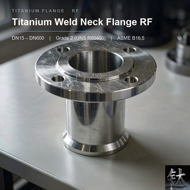
Request a Quote for Titanium, Nickel or Zirconium
Tell us what you need. Send the points below and we reply with live stock status, price and lead time — usually the same day.
Send us these 6 points (or just attach your drawing / old supplier spec)
| 1 | Material grade — Gr2 / Gr5 / Gr7 / Gr12, Ni200 / Ni201 / Monel 400, Zr702… |
| 2 | Form — plate / tube / bar / wire / fitting / flange / fastener / equipment |
| 3 | Size & tolerance — thickness×width×length / OD×WT / diameter |
| 4 | Quantity — kg / pcs / m (small batch and non-standard sizes welcome) |
| 5 | Standard — ASTM B265 / B338 / B348, ASME B16.5, EN 1092-1… |
| 6 | Application & destination — helps us pick the right grade and certifications |
Not sure how to fill this? Send your drawing or an old supplier's specification sheet — we will break it down for you.
Reach us directly
Email: [email protected]
WhatsApp / WeChat:+8618829679311 leave your number on the form
Or use the inquiry form on this page — attach your drawing and we will respond within one business day.
Why buyers come to us
Stock holder in Baoji Titanium Valley with ~800 t inventory · cut-to-size and small batch · drawing-based machining for non-standard parts · we read ASTM / ASME / GB specs · export experience · same-day response on quotes.
Tell us your requirement — grade, size and quantity. We reply within 24 hours.
Prefer chat? WhatsApp +86 188 2967 9311 or email [email protected].
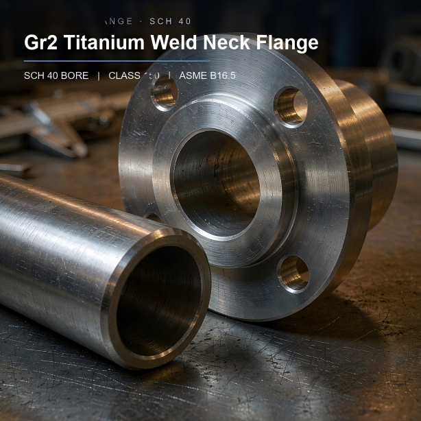

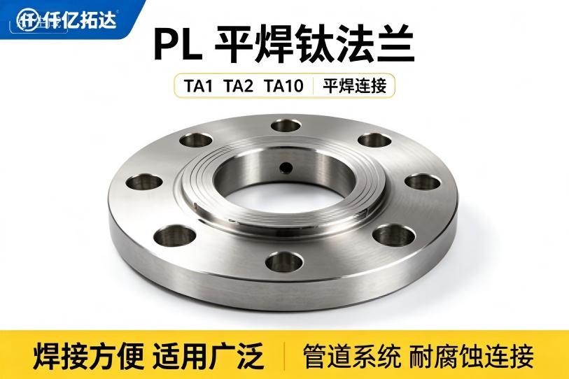

- Titanium Price Today (9 Nov 2026): Plate, Tube, Rod & Wire
- What is Titanium Flange | ASME B16.5 ASTM B381 Gr2 Gr5 Titanium Flan
- ASME B16.5 Titanium Flange Grade2 DN100-DN600 Class150/300 FOB
- Gr2 Titanium Sheet Price FOB Shanghai | ASTM B265 In Stock
- Titanium Price Today (Oct 26, 2026): China Market Report
Contact Person: Wang Xiaoning
Tel: +86-917-355-7966
Email: [email protected]
WhatsApp: +86 188 2967 9311
Company: Shaanxi Qianyi Tuoda Technology Co., Ltd
Address: Floor 4, Building 4, No. 188 Gaoxin Avenue, High-tech Zone, Baoji City, Shaanxi Province, China