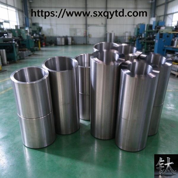
Titanium Weld NDT and WPS Qualification: How to Prove a Titanium Weld Is Actually Sound
| Спецификация | ASME BPVC Section IX / V / VIII-1 |
|---|---|
| Применимый стандарт | WPS / PQR / WPQ |
| Состояние материала | titanium weld NDT: RT / UT / PT / PAUT |
| Контроль и упаковка | acceptance criteria UW-51 / ISO 5817 |
Описание продукции: WPS, PQR and WPQ under ASME IX; which NDT method finds which defect; why UW-51, ISO 5817, API 1104 and AWS D1.1 disagree. 8 failure modes
Обзор продукции
Titanium Weld NDT and WPS Qualification: How to Prove a Titanium Weld Is Actually Sound
A titanium pressure weld is only as good as the paperwork that proves it — and most of that paperwork is assembled in the wrong order. Under ASME BPVC Section VIII Division 1, taking full radiography on a Type 1 butt weld gives a joint efficiency of E = 1.00; spot radiography gives 0.85 and no radiography 0.70. That single number sets the shell thickness, so the inspection regime is a design decision, not a QA afterthought. This article is about the system behind a sound titanium weld: what a WPS, PQR and WPQ actually qualify, which NDT method finds which defect, why the four common acceptance standards do not agree, and the eight ways this system breaks in real orders. It is the downstream half of our GTAW shielding and back-purge guide (how to make the weld) and the companion to our tube-to-tubesheet welded detail page (a ready-to-copy RFQ checklist for that one joint). Here we deal with the qualification logic and the acceptance rules that apply to every weld on the vessel.
At a Glance: A Paper-Qualified Weld vs a Verified One
| Item | Paper-qualified (common) | Actually verified (what to buy) |
|---|---|---|
| Procedure | "WPS available on request", no supporting coupon record | WPS with a named PQR, actual test values and tensile / bend results |
| Welder | Generic "certified welders", or a certificate from a previous employer | WPQ in the employer’s own name, in-date continuity, qualified P-No and position |
| Examination | Visual + colour check only, report issued at dispatch | PT plus volumetric RT / UT at the extent tied to the joint efficiency E |
| Acceptance | "No cracks", or a limit copied from a different code | Named standard + edition + clause (e.g. ASME VIII-1 UW-51, current edition) |
| Timing | NDT immediately after welding, before delayed cracking can appear | Final NDT after the hold time in the ITP (commonly 24-48 h on titanium) |
| Repair | Grind out, re-weld, re-weld again, no location log | Excavate to sound metal, cap on repairs per area, extended re-examination |
| Records | Certificate folder assembled after the order ships | Weld map, heat cross-link, TPI witness at hold points front-loaded in the PO |
The “We Have a Certificate” Trap
The most expensive sentence in a titanium equipment enquiry is "we are ASME certified, certificates will be provided". It sounds complete and it verifies almost nothing about the welds on your specific vessel. ASME does not issue a "Section IX certificate" to a fabricator: Section IX is a qualification standard, and the records it produces (the WPS, its supporting PQR, and each welder's WPQ) are issued by the employer, not by ASME. For ASME code construction an Authorized Inspector reviews that the file exists and matches production. There is no registrar and no stamp to ask for. What you can ask for is concrete: the WPS/PQR index for the alloy and process on your order, the essential-variable ranges on each WPS, the welder continuity log, and the examination extent that matches the joint efficiency claimed in the design calculation.
Two consequences follow. First, a supplier who can only produce a generic company certificate cannot demonstrate that a specific Gr2 GTAW procedure with a trailing shield was ever qualified. Second, the certificates that arrive in a folder after dispatch are far weaker than the same records front-loaded into the purchase order with third-party witness points. Our three-step arrival acceptance list covers the buyer-side receiving check (MTC, dimensions, whether the reports are present); this article covers what those reports must actually contain to mean anything.
Ask for these five documents, not one certificate: (1) the WPS with its revision and essential-variable ranges; (2) the supporting PQR with actual coupon parameters and tensile / bend / impact results; (3) the WPQ for each welder, in the fabricator's own name, with a continuity log; (4) the weld map with heat numbers cross-linked to the EN 10204 3.1 mill certificates; (5) the NDT procedures, extent, acceptance standard with edition, and the repair log.
What ASME Section IX Actually Qualifies: WPS, PQR and WPQ
Section IX answers exactly two questions: does this procedure produce a weld with acceptable mechanical properties, and can this individual welder execute it. It does not tell you what to weld, how strong the joint must be, or what examination to perform — those come from the referencing construction code (Section VIII, B31.3, B31.1) and from your specification. The document chain is strict: a preliminary WPS is written, a coupon is welded under recorded conditions, the coupon is destructively tested, and the resulting PQR becomes the permanent evidence that supports the production WPS. A WPS with no supporting PQR has no validity. One PQR can support several WPSs within its qualified ranges, and one WPS can draw on several PQRs.
Typical groove-weld procedure qualification requires two tension specimens and four guided bends (face and root, or side bends for thick material), plus Charpy impacts only where the construction code makes notch toughness a requirement. Essential variables are the parameters whose change forces a new PQR: welding process, base-metal P-Number, filler F-Number or A-Number, qualified thickness range, a substantial reduction in preheat, and adding or deleting PWHT. Supplementary essential variables (position, heat input, interpass, PWHT time and temperature) become controlling only when impact testing is required. Nonessential variables such as groove angle, backing method or electrode diameter can be revised on the WPS without re-testing.
Welder performance qualification (WPQ, also written WPQR) is narrower and skill-based: the named welder deposits a coupon to the already-qualified WPS, examined by guided bends or radiography, and the resulting certificate fixes that welder's ranges for process, P-Number, thickness, position, backing and pipe diameter. Continuity matters operationally: if the welder does not use the process within the code window, commonly six months, the qualification lapses and welds made afterwards are not acceptable. In commercial terms, a GTAW PQR is often quoted in the low thousands of dollars and one to three weeks for a straightforward coupon, while impact-tested nickel-alloy procedures or a large welder roster can run to one to three months. That is a schedule gate, not a preference, so ask for the index before you agree a delivery date.
The qualification framework is not universal. ASME Section IX governs ASME code construction; ISO 15614-5 (procedure qualification for titanium and zirconium alloys) with ISO 9606 (welder qualification) is the European PED route; AWS D17.1 covers aerospace. The concepts are parallel but the variable classifications and the ranges each qualification covers differ, so an ASME IX requirement cannot be satisfied by an ISO 15614 file without explicit agreement. State the required system in the enquiry and verify it at document review — do not let the supplier pick whichever file happens to be on the shelf. Filler selection feeds into this too: ERTi-2 versus ERTi-7 or ERTi-12 changes the F-Number and the qualified group, which is why our welding wire selection guide and ASTM B863 wire guide belong in the same review.
Why Weld Colour Is Not an NDT Method
Titanium starts picking up oxygen and nitrogen well before the metal melts, and the oxide film thickens predictably with both temperature and exposure. That makes weld colour an excellent process indicator: a silvery or light-straw bead says the torch, trailing shield and back purge all worked; blue, purple, grey or a white powdery scale says the shielding failed somewhere. It is fast, free, and available on every weld. It is also not an examination method. Colour tells you about the atmosphere around a hot bead, not about porosity, lack of fusion, tungsten inclusions or a crack two millimetres below the surface. A perfectly silver root can still hide a lack of side-wall fusion that opens under vibration; a slightly straw-coloured cap can be entirely sound.
The trap is treating one as a substitute for the other. On titanium tube and pipe, published failure reviews repeatedly put the majority of early leaks at the weld — our TA2 tube weld-protection failure analysis collects the three recurring causes (oxide colour from poor back purge, needle porosity and tungsten inclusion from poor groove cleaning, and vibration fatigue). Colour control prevents the first; only NDT finds the second and third. On thin-wall tube, eddy-current or ultrasonic testing online, plus a final hydrostatic test with controlled chloride in the test water, is what actually closes the loop. Our ASTM B338 tube ordering guide and welded versus seamless tube guide set out where each examination belongs in the order.
There is a real disagreement worth knowing about. Many shop specifications and project documents state flatly that any blue or purple bead must be removed and re-welded, never ground and accepted. Other published guidance says a purple tint is not automatically a reject and must be judged against the specific standard clause cited in the project. Both positions exist in industry, and the difference is not academic — it decides whether a whole tube bundle is scrapped. We do not resolve it here with a made-up universal threshold. Instead: write the colour acceptance clause, with its source and edition, into the ITP before welding starts, and require a documented visual record. Where the clause is absent, the conservative route (remove and re-weld) is cheaper than arguing about a leaked exchanger a year later, which is the pattern in our tube-bundle failure case collection.
The P-Number Trap: Where Published Tables Disagree
ASME Section IX groups base metals into P-Numbers so one qualification can cover a family instead of one grade at a time. That grouping is exactly where titanium orders go wrong, because the published tables do not agree with each other. One widely used supplier reference assigns commercially pure Grades 1 and 2 and Grade 12 to P-No. 51 / 52 splits, with Grade 7 and Grade 12 under P-52; a technical reference on titanium welding puts all CP Grades 1–4 and Grade 5 under P-No. 51 (Grade 5 as Group 1), with beta alloys possibly P-53; and a long-standing AWS forum answer quoting the 1998 edition of QW-422 gives Grades 1, 2 and 7 as P-51, Grades 3 and 12 as P-52, and Grade 9 as P-53. F-Number / SFA-Number groupings for ERTi fillers show the same version drift.
We are not going to print a single "correct" table, because the honest answer is that these assignments changed between code editions and the authoritative source is the current QW/QB-422 and QW-432 in the edition named in your contract. What matters commercially is the consequence. If the WPS claims P-51 but the production material is a grade your code edition places in P-52, the procedure may not cover the weld at all — and the fabricator may not have noticed, because the certificate looks fine. The same error appears when a Gr9 hydraulic or seamless tube is substituted into a job qualified on CP Grade 2, or when a Grade 7 upgrade for a hot crevice condition quietly changes the qualified group without a new PQR.
Write this into the enquiry: "State the ASME BPVC Section IX edition used for qualification. For each WPS, list the P-Number / Group Number, F-Number and A-Number actually recorded on the supporting PQR, and confirm they cover every base metal and filler on this order (including any Grade 7 / Grade 9 / Grade 12 upgrade). Attach the PQR index." Cross-check the WPS against the plate MTR and the 3.1 certificate heat numbers, not against a catalogue table.
This is the same discipline as any other alloy upgrade. Our tube-sheet material selection guide and welded tube-to-tubesheet detail both make the point that changing the alloy to solve a corrosion problem is also a change to the qualification basis. When the fix is "use Grade 7 instead of Grade 2 above 80 °C in deaerated brine", the WPS/PQR file has to move with it.
Which NDT Method Finds What — and What Each One Misses
No single method clears a weld. The useful way to read an inspection plan is by defect geometry: volumetric flaws (porosity, slag, tungsten inclusions) versus planar flaws (lack of fusion, cracks) versus surface-opening flaws versus through-leakage. Radiography is strong on volumetric flaws and gives a permanent film or digital image, but a tight lack of fusion lying parallel to the beam can be nearly invisible. Ultrasonics, especially PAUT and TOFD, is the method for planar flaws and through-thickness sizing, but it needs a written qualified procedure and operators who have demonstrated on a representative block. Penetrant testing only sees defects open to the surface. A hydrostatic test proves the vessel holds pressure, not that a 3 mm pore is absent.
| Method | Finds well | Misses / limitation | Typical place on titanium |
|---|---|---|---|
| VT + colour | Shielding failure, heat tint, undercut, reinforcement, spatter | Anything sub-surface; subjective without a written colour clause | Every weld, 100%, before and after any repair |
| PT (dye penetrant) | Surface-breaking cracks, pinholes, lack of fusion reaching the face | Buried porosity, internal lack of fusion; chlorinated penetrants harm titanium | Root and cap, nozzle and attachment welds, after final cleaning |
| RT (radiography) | Volumetric defects: porosity, slag, tungsten inclusions; permanent image | Planar lack of fusion and tight cracks unfavourably oriented to the beam | Category A / B butt welds; extent set by UW-11 and joint efficiency |
| UT / PAUT / TOFD | Planar defects, lack of fusion, crack sizing through thickness | Needs a qualified procedure and demonstration-qualified operators; owner spec often still demands RT | Thick sections, nozzle necks, clad interfaces, where RT is impractical |
| ET (eddy current) | Longitudinal defects in thin-wall tube, high speed, online | Limited to conductive thin sections; geometry-sensitive | Welded tube mill, heat-exchanger tube stock |
| Helium leak test | Micro-leaks a hydrostatic test will miss | Gives no defect size or location; slow and needs access to both sides | Chlor-alkali, lithium brine, marine critical joints |
| Hydrostatic test | Gross integrity, gross leakage, global strength (commonly 1.5× design pressure) | Does not size or locate small flaws; test-water chloride must be controlled | Final check after NDT, before surface finish and packing |
Two titanium-specific details belong in the plan. First, penetrant chemistry: chloride-bearing penetrants, cleaners and developers are a crevice-corrosion starter on titanium, so specify a non-chlorinated system and a documented post-test rinse and dry. This connects directly to the surface-cleanliness work in our GTAW shielding guide and the receiving checks in the arrival acceptance list. Second, hardness is a useful auxiliary indicator on titanium: an unexpected rise in weld or HAZ hardness usually means interstitial pickup (oxygen / nitrogen / hydrogen) rather than a heat-treatment effect, and it justifies a hydrogen check even when the radiograph is clean.
Substitution is allowed but not automatic. ASME Code Case 2235, since incorporated into Section VIII Division 1 Mandatory Appendix 12 and Division 2 Mandatory Appendix 9, permits PAUT or TOFD in lieu of RT where the procedure is qualified to Section V Article 4 mandatory appendices, personnel are demonstration-qualified, and the acceptance criteria are met. Many owner specifications still require RT regardless of what the code permits. If you want UT instead of RT on a thick titanium nozzle, the project specification must say so explicitly; a fabricator cannot assume it. For routine documentation evidence, our flange with RT test report page shows the kind of report package a buyer should expect, and our heat-exchanger 3.1 MTC page shows how it ties into the material dossier.
The Four Acceptance Standards That Do Not Agree
Here is the part of the specification that generates the most disputes at the first audit: the acceptance limits are not transferable between codes. All four reject cracks and lack of fusion outright, but they differ on the size of an acceptable pore, how elongated indications are summed, the reference length over which a cluster is judged, and even which thickness the limit is keyed to. ISO 10675-1 works on a 100 mm reference length; ASME practice is commonly quoted around 150 mm; API 1104 and AWS D1.1 use 300 mm. A scatter of small pores that passes a 300 mm zone criterion can fail a 100 mm one, and vice versa when the cluster is tight.
| Reference | Typical domain | How it sets limits | Reference zone |
|---|---|---|---|
| ASME VIII-1 UW-51 / UW-52 | Pressure vessels, full / spot RT | Linear and rounded indication limits keyed to weld thickness; cracks and lack of fusion rejected outright | Of the order of 150 mm |
| ISO 5817 / ISO 10675-1 | Quality levels B / C / D; explicitly covers steel, nickel and titanium alloys | Imperfection quality levels plus RT acceptance levels; pore diameter and projected area by level | 100 mm reference length |
| API 1104 §9 | Cross-country and offshore pipelines | Defect-type-specific limits; single pore no more than t/4 or 3.2 mm; density comparison chart | 300 mm |
| AWS D1.1 §6.12 | Structural steel, statically vs cyclically loaded | Cyclic loading far stricter (individual pores above 2 mm rejected); incomplete penetration in tension members rejected | 300 mm combined |
Three interpretation errors recur. Under-reporting clustered porosity: an interpreter who judges each pore in isolation can accept a scatter that collectively exceeds the zone-density criterion — the zone limit must be applied to every window along the full weld length. Misidentifying the indication: a tight crack with sharp or branching ends must be judged against the categorical crack rejection, not the more permissive elongated-slag limit. Using the wrong thickness: acceptance tables step on weld thickness (throat or groove depth for partial-penetration joints), not on base-metal plate thickness; using the latter applies a looser limit and can accept a rejectable weld.
There is an extra wrinkle for titanium. ISO 5817:2023 is titled for fusion-welded joints in steel, nickel, titanium and their alloys, so it is a legitimate acceptance reference for titanium work; ASME UW-51 comes from the pressure-vessel construction code and is the usual reference on an ASME-stamped vessel; API 1104 and AWS D1.1 belong to pipeline and structural work and are frequently cited by mistake on process equipment. Specifying the wrong code as the acceptance reference is one of the most common procurement-document errors, and it surfaces at the first Authorized Inspector audit.
Do not write: "Welds to be free of defects, NDT to international standard." Write: "Radiographic examination of Category A and B butt welds: 100% (full RT). Acceptance: ASME BPVC Section VIII Div.1 UW-51, [edition year], including Mandatory Appendix 4 for rounded indications. Technique: Section V Article 2. Any substitution of PAUT for RT requires written approval of the purchaser and the Authorized Inspector before production." Name the standard, the edition and the clause; the edition matters because thickness steps and alloy exceptions change between revisions.
The same applies to documented evidence. A report that says "RT passed" with no technique sheet, no IQI sensitivity, no film density and no acceptance reference is a statement, not a record. Section V Article 2 technique requirements (including roughly 2% IQI sensitivity and a controlled density range) are what make the image interpretable at all. Buyers who want a compact checklist for reviewing the paperwork can use our arrival acceptance three-step list; the point here is that the review has to name a standard before it can check compliance with one.
Joint Efficiency Drives the Inspection Regime, Not the Other Way Round
Buyers often assume the inspection percentage is negotiated at the end, as a QA line item. On an ASME VIII Division 1 vessel it is fixed upstream by the design: the joint efficiency E appears in the UG-27 shell-thickness equation, and E is only available at a given value if the corresponding radiography is actually performed and documented. Taking the full-RT credit reduces the required wall thickness and therefore material cost, at the price of examining every Category A and B butt weld. Choosing no RT thickens the vessel. The economics run in both directions, which is why this decision belongs in the enquiry, not in a change order three weeks before dispatch.
| RT category (UW-11) | Extent | Joint efficiency E, Type 1 butt joint | Design consequence |
|---|---|---|---|
| Full RT — UW-11(a) | 100% of Category A and B butt welds | 1.00 | Thinnest shell, most inspection cost |
| Spot RT — UW-11(b) | At least one 150 mm (6 in.) spot per welder per 15 m (50 ft) of weld | 0.85 | Mid: thicker wall, moderate NDT |
| No RT — UW-11(c) | No radiographic examination | 0.70 | Thickest shell; alignment rules apply |
Several situations force full radiography regardless of the economic choice: lethal service under UW-2(a), unfired steam boilers above roughly 50 psi, thick joints in P-1 materials above about 38 mm (1.5 in.), and certain design-temperature / impact-test combinations. Note also that Type 1 is not the only joint type: a single-welded butt joint with a backing strip left in place (Type 2) tops out at E = 0.90 even with full RT, and lap-joint types cannot be upgraded by radiography at all. Seamless shell sections are frequently misapplied here too — under UW-12(d) a seamless section is 0.85, not 1.00, unless the required spot examination is actually performed and documented.
For process piping rather than vessels, ASME B31.3 sets its own examination extent (commonly 100% visual with a specified random RT fraction depending on the fluid service and piping class), so do not copy the vessel table onto a pipe spool. And for the examination report itself, remember that the acceptance criteria for ASME work live in UW-51 / UW-52 in Section VIII, while the technique requirements live in Section V. Conflating the two is a routine documentation error. Our non-standard titanium process equipment guide sets out where these code boundaries land on a typical fabricated package, and our titanium flange guide covers the bolted interfaces that sit just outside the weld category system.
Limitations and Failure Conditions: Where the System Breaks
A qualification file and an NDT report are evidence, not immunity. The eight situations below are organised by how they appear in real orders and audits rather than by discipline, and each one has produced a rejected vessel or an in-service leak whose material certificate was entirely correct. None of them is fixed by adding another certificate; all of them are fixed by writing the right requirement into the ITP before the first arc is struck.
An essential variable changed after the PQR was signed
The single most common qualification failure. A fabricator qualifies GTAW with a trailing shield on Grade 2 plate, then switches to plasma arc, changes to a filler with a different F-Number, welds outside the qualified thickness range, or quietly drops PWHT — and keeps using the same WPS. Each of those is an essential-variable change that requires a new PQR. The certificate folder still looks complete, because nobody revoked the WPS. Check the WPS ranges against the actual production parameters on the weld map, and ask for the revision history rather than the current issue alone.
A welder qualification borrowed from another employer or another alloy
A WPQ belongs to the employer who tested and records the welder; a certificate from a previous employer is not portable without the new employer's own qualification. Nor does a qualification on carbon steel or austenitic stainless carry over to titanium, because the P-Number grouping is different. Continuity is the second half of the problem: if the welder has not used the process for the code window (commonly six months), the qualification lapses. On a project with a long gap between orders, this is easy to miss and expensive to discover during an audit — see the B863 wire and welder qualification guide for how filler and welder ranges are recorded together.
PT passed, but a planar lack of fusion is still inside
Titanium GTAW is run at low heat input with a small bead and fast travel speed to protect the shielding envelope, which is precisely the regime where side-wall fusion can be marginal. Penetrant testing only sees defects open to the examined surface, and radiography is weak on planar flaws unfavourably oriented to the beam. A weld can pass 100% VT and PT, show a perfect silver colour, and still carry a lack-of-fusion plane that opens under vibration or thermal cycling. Where the joint is a full-penetration butt weld in cyclic service, specify volumetric examination (RT or qualified PAUT/TOFD) and consider an angle-beam UT pass specifically for planar defects; the failure pattern is documented in our weld protection failure analysis and the tube-bundle case collection.
Final NDT performed before delayed hydrogen cracking can appear
Hydrogen and moisture picked up from humid air, damp filler, incompletely dried joint faces or hydrocarbon residue can produce delayed cracking in titanium welds hours to days after welding. If the final radiograph or ultrasonic scan is taken immediately after the bead cools, it can be entirely clean and still miss a crack that develops later. Project specifications commonly impose a hold of roughly 24–48 hours before final NDT on titanium; the exact figure is not universal and should be taken from the ITP and the applicable construction code, not from a generic table. Record the weld completion time and the examination time on the report so the hold is auditable. Our GTAW shielding and back-purge guide covers preventing the hydrogen pickup in the first place.
Repair welding repeated beyond the project limit, with no location log
Codes do not give one universal number for how many times a given spot may be repaired; the cap is set by the project specification and by the construction code. Every repair cycle adds a thermal cycle to the same HAZ, coarsens grains, accumulates residual strain and increases interstitial pickup risk. A defensible rule is: fully excavate to sound metal (verified by PT), clean the cavity, re-weld under the same qualified WPS, log the location and the repair number, re-examine by the original method over an extended length, and escalate to engineering review once the cap is reached. Grinding a discoloured bead smooth and accepting it is not a repair — the coloured oxide is a symptom of contamination that remains in the metal.
Chlorinated penetrant, halide residue and missing post-NDT cleaning
An inspection step can itself create the corrosion problem. Chlorinated penetrants, developers and solvent cleaners leave halide residues that are crevice-corrosion starters on titanium, particularly in hot chloride or brine service. Specify a non-chlorinated PT system, a documented final rinse with controlled chloride and thorough drying, and a record that the part was cleaned after examination rather than packed wet in the test bay. The same caution applies to hydrostatic test water: chloride content and drainage / drying after the test belong in the procedure. This links directly to the surface-cleanliness discipline in our shielding guide and the receiving checks in the arrival acceptance list.
NDT done after hydrotest, or TPI witness points back-issued
Sequence errors are cheap to prevent and hard to fix on paper. Volumetric and surface NDT belong before the hydrostatic test and before final surface finishing or coating; a report dated after the hydrotest invites the question of what was examined. Third-party inspection (TPI) hold points and a 3.2 certificate with a named body (SGS / BV / TÜV and similar) must be written into the PO up front: a witness point cannot be back-issued after the weld is closed, and a 3.2 dossier cannot honestly be assembled from a 3.1 mill certificate afterwards. The weld map, heat cross-link to the heat-exchanger 3.1 MTC, expansion logs, gas-shield records and examination reports form one chronological chain — see our welded tube-to-tubesheet detail for how that chain is documented per joint.
Acceptance criteria quoted from the wrong code or the wrong edition
This is the failure that appears at the first Authorized Inspector audit. A specification that copies API 1104 pore limits onto an ASME VIII vessel, judges an ISO 5817 quality level against a 300 mm API reference zone, reads the acceptance table using base-plate thickness instead of weld thickness, or uses a P-Number grouping from a superseded Section IX edition has no defensible acceptance basis. All four standards reject cracks and lack of fusion, but their numeric limits and reference lengths differ. Name the standard, the edition year and the clause in the PO; require the technique sheet and the interpreter's qualification with the report; and re-confirm the edition at contract review, because revisions change thickness steps and alloy exceptions.
Application Map and How to Specify
Match the verification package to the consequence of a leak and to the construction code that governs the item. A low-pressure Grade 2 process tube spool and a lethal-service reactor both need a qualified WPS, but the examination extent, the acceptance reference and the third-party witness points are different orders of magnitude. The table below is a starting point for the enquiry, not a substitute for the design code.
| Duty / construction | Minimum defensible package | What buyers usually forget |
|---|---|---|
| ASME VIII-1 pressure vessel, non-lethal service | WPS + PQR + WPQ, full or spot RT to the claimed E, PT on attachments, hydrotest, MDR | Naming the acceptance clause + edition; welder continuity log |
| Lethal / chlor-alkali / lithium brine duty | Full RT (mandatory), 100% PT, helium leak test on critical joints, non-chlorinated consumables | Hold time before final NDT; post-test rinse and dry record |
| Heat-exchanger tube bundle | ET / UT on tube stock, tube-to-tubesheet weld map, expansion log, leak test, 3.1 / 3.2 dossier | Heat-number cross-link tube ↔ tubesheet ↔ MTC; qualified procedure for each joint form |
| Process piping (B31.3) | 100% VT plus the code-required random RT fraction, PT on socket / attachment welds | Not copying the vessel UW-11 table onto pipe spools |
| Aerospace / medical hardware | AWS D17.1 or ISO 15614-5 / ISO 9606 route as specified, full traceability, often F136 chemistry on implants | That ASME IX and ISO qualification files are not interchangeable |
One practical note on scope: this article concerns the qualification and acceptance system for welds across the vessel. For the specific case of a tube-to-tubesheet joint, including the roll-then-weld sequence, the ≥3.2 mm roll-to-weld clearance, non-chlorinated PT, helium leak targets and a copy-paste RFQ checklist, use our dedicated welded tube-to-tubesheet detail page instead. For choosing the tube-sheet material or cladding in the first place, see the five-material tube-sheet selection guide.
How to Write It Into the ITP and Purchase Order
The whole system collapses if the requirements are agreed verbally and reconstructed at dispatch. Put them in the Inspection and Test Plan with named hold points and a document list. At minimum the ITP should state: the qualification system and code edition; the WPS/PQR numbers that will be used; the examination methods and extent for each weld category; the acceptance standard with edition and clause; the timing (including any hold before final NDT); the repair cap and re-examination rule; the TPI witness / hold / review points; and the final documentation dossier. Then make the PO reference the ITP revision, so a later "updated" ITP cannot quietly reduce the examination extent.
Copy-paste enquiry wording: "Welding: GTAW with trailing shield and documented back purge. Qualification to ASME BPVC Section IX [edition]; submit WPS/PQR index, PQR test results, welder WPQ and continuity log for approval before production. Base metals: ASTM B265 Gr___ / B338 Gr___ [state every grade incl. any Gr7 / Gr9 / Gr12 upgrade]; confirm P-No / Group and F-No coverage. Examination: 100% VT and colour record; PT (non-chlorinated system, documented rinse and dry) on all attachment and nozzle welds; RT of Category A and B butt welds [full 100% / spot per UW-11(b)] with acceptance to ASME VIII-1 UW-51 [edition]; final NDT not before [24-48] h after welding. Repairs: excavate to sound metal, PT-verify, log location and count, cap of [__] per joint, extended re-examination. Hydrostatic test at 1.5× design pressure with chloride-controlled water, after NDT. Documentation: weld map, heat cross-link to EN 10204 3.1 MTC, NDT reports with technique sheets, repair log, MDR 3.2 with [TPI body] witness at hold points named in the PO."
Two habits make this work. First, ask for the PQR index at enquiry stage, because a fabricator without a qualified procedure for your alloy and process cannot start — that is a lead-time fact, not a document preference. Second, tie the examination extent to the design calculation: if the drawing claims E = 1.00, the ITP must say full RT, and the report package must contain enough films or digital images to prove it. Our process equipment buyers guide and 3.1 / 3.2 documentation page show what a complete dossier looks like when it arrives.
Summary: Choose Full Volumetric Examination if, Choose a Lighter Package if
Choose full RT (or explicitly authorised PAUT / TOFD) + 100% PT + witnessed hydrotest if:
- The design takes a joint efficiency of E = 1.00, or the service is lethal, chlor-alkali, lithium brine or otherwise unforgiving.
- The weld is a full-penetration butt joint in cyclic, vibrating or thermally cycling service where planar lack of fusion is the credible failure mode.
- The vessel is thick-walled, or its geometry makes a later repair disproportionately expensive.
- A regulator, owner specification or third-party insurer requires full examination and a 3.2 dossier with named witness points.
- The cost of one unplanned shutdown exceeds the entire inspection budget — which is true for most chemical-process equipment.
Choose spot RT / a lighter documented package if:
- The design legitimately uses E = 0.85 or 0.70 and the thicker wall has been calculated, not assumed.
- The item is a low-pressure, non-lethal, non-cyclic spool with a mild dry duty and no crevice condition.
- 100% VT plus PT plus a hydrostatic test already covers the credible defects, and the construction code permits the reduced extent.
- You can still name the acceptance standard and edition — a lighter package is never a vaguer one.
-
The one-line rule: a weld is not qualified by a certificate, it is qualified by a traceable chain — WPS backed by PQR, a welder in date, an examination method matched to the defect geometry, an acceptance clause with its edition, and a record assembled before the vessel closes. We hold roughly 800 tonnes of titanium, nickel and zirconium stock in Baoji, cut to non-standard sizes, work from customer drawings, certify to ASTM / ASME / GB with traceable MTR and PMI, and ship export orders the same day. If you want the qualification and examination package specified as carefully as the alloy, tell us the construction code, the joint categories, the claimed joint efficiency and who will witness the hold points; we will quote the material and the documentation together. Request a quote →
Frequently Asked Questions
Does a fabricator need an "ASME Section IX certificate"?
No. ASME does not issue a Section IX certificate or stamp to a shop; Section IX is a qualification standard and the WPS, PQR and WPQ records are issued by the employer, with the Authorized Inspector checking that the file exists and matches production for code construction. Ask instead for the WPS/PQR index for your alloy and process, the essential-variable ranges, the welder continuity log and the examination extent tied to the joint efficiency claimed in the design.
Can a supplier use a WPS qualified for stainless or carbon steel on titanium?
No. P-Number groupings exist precisely because weldability and mechanical response differ; a qualification on P-No. 1 carbon steel or P-No. 8 austenitic stainless does not cover titanium. Published P-Number assignments for titanium grades also differ between code editions (CP Grades 1-4 are commonly P-51, with Grade 9 and Grade 12 variously listed under P-52 or P-53), so require the fabricator to state the Section IX edition and confirm that the P-No / Group and F-No on the PQR cover every base metal and filler on your order. A welder qualification is likewise employer-specific and cannot simply be transferred from another company.
Are ASME Section IX and ISO 15614-5 / ISO 9606 interchangeable?
No. ASME Section IX governs procedure and performance qualification for ASME code construction, while ISO 15614-5 (procedure qualification for titanium and zirconium alloys) and ISO 9606 (welder qualification) are the European PED route; AWS D17.1 applies to aerospace. The underlying concepts are parallel but the variable classifications and the ranges each qualification covers differ, so an ASME IX requirement cannot be met by an ISO file without explicit agreement. State the required system in the enquiry and verify it at document review.
Why is penetrant testing not enough, and when is RT or UT required?
PT only detects defects open to the examined surface. Titanium GTAW is run at low heat input to preserve gas shielding, which is exactly the regime where buried side-wall lack of fusion can occur; radiography is strong on volumetric porosity and tungsten inclusions but weak on planar flaws unfavourably oriented to the beam, while UT / PAUT / TOFD is the method for planar defects. For ASME VIII-1 vessels the extent is set by UW-11 and the joint efficiency: full RT gives E = 1.00, spot RT 0.85 and no RT 0.70. PAUT in lieu of RT is permitted under Mandatory Appendix 12 only with a qualified procedure, demonstration-qualified operators and explicit owner-specification authorisation.
How long should we wait before final NDT on a titanium weld?
Titanium welds can develop delayed hydrogen cracking from moisture, damp filler or hydrocarbon residue on the joint faces, so an immediate post-weld radiograph can be clean and still miss a crack that appears later. Project specifications commonly impose a hold of roughly 24-48 hours before final NDT; there is no single universal figure, so take the value from the ITP and the applicable construction code and record both the weld completion time and the examination time on the report. Preventing hydrogen pickup through proper shielding, dry consumables and clean joint faces is more effective than any hold time.
How many times can a weld be repaired?
The construction codes do not give one universal number; the cap is set by the project specification and must be written into the ITP. Each repair cycle re-heats the same HAZ, coarsens grains, accumulates residual strain and adds interstitial-pickup risk. A defensible sequence is to excavate to sound metal and verify by PT, clean the cavity, re-weld under the same qualified WPS, log the location and repair count, re-examine by the original method over an extended length, and escalate to engineering review at the cap. A discoloured bead must be removed and re-welded, never ground smooth and accepted, because the colour signals contamination in the metal.
Should the acceptance standard be ASME UW-51, ISO 5817, API 1104 or AWS D1.1?
It is set by the construction code and the contract, and the four are not interchangeable. ASME VIII-1 UW-51 / UW-52 governs pressure-vessel radiography; ISO 5817:2023 with ISO 10675-1 gives quality levels B/C/D and explicitly covers steel, nickel, titanium and their alloys; API 1104 section 9 is for pipelines; AWS D1.1 section 6.12 is for structural steel and is far stricter for cyclically loaded members. They differ on pore size, how elongated indications are summed and the reference length (roughly 100, 150 and 300 mm respectively). Name the standard, edition year and clause in the PO, and never judge a weld against a limit copied from another code.
Опишите ваши требования — марка, размер и количество. Ответим в течение 24 часов.
Предпочитаете чат? WhatsApp +86 188 2967 9311 или напишите на sales@sxqytd.com.
- Что такое титан фланец| ASME B16.5 ASTM B381 Gr2 Gr5 титановые флажк
- ASME B16.5 титановая флажка класса 2 DN100-DN600 Класс 150/300 FOB
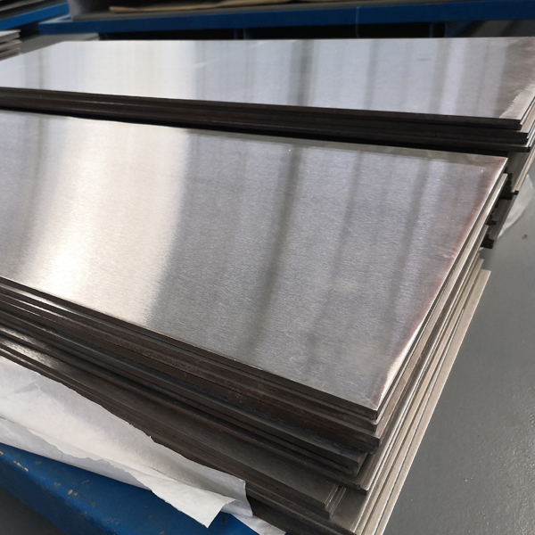
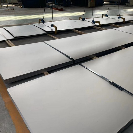
- Gr2 Titanium Sheet Price FOB Shanghai | ASTM B265 In Stock
- Titanium Price Today (26 октября 2026 г.): отчет о рынке Китая
- Цена на титан сегодня (23 октября 2026 г.): пластина, трубка, стерже
Контактное лицо: Wang Xiaoning
Телефон: +86-917-355-7966
Эл. почта: sales@sxqytd.com
WhatsApp: +86 188 2967 9311
Компания: Shaanxi Qianyi Tuoda Technology Co., Ltd
Адрес: Floor 4, Building 4, No. 188 Gaoxin Avenue, High-tech Zone, Baoji City, Shaanxi Province, China